
Asynchronous Decade Counters, method of partial decoding & glitch
In this post, we will discuss Asynchronous Decade Counters. To start with we will briefly see what an asynchronous counter is and then we will find what a decade counter is.
In a binary counter, if flip-flops do not change states in exact synchronism with the applied clock pulses then the counter is called asynchronous binary counter. In this counter, each FF output drives the CLK input of the next FF.
Now, to understand a decade counter, we need to understand a few more terms like (1) modulus of a counter, (2) states, & (3) truncated sequence.
The modulus of a counter is the number of unique states through which the counter will sequence. The maximum possible number of states (maximum modulus) of a counter is 2n , where n is the number of flip-flops in the counter.
Counters can be designed to have a number of states in their sequence that is less than the maximum of 2 n. This type of sequence is called a truncated sequence.
One common modulus for counters with truncated sequences is ten (called MOD10).
Counters with ten states in their sequence are called decade counters. A decade counter with a count sequence of zero (0000) through nine (1001) is a BCD decade counter because its ten-state sequence produces the BCD code. This type of counter is useful in display applications in which BCD is required for conversion to a decimal readout.
To obtain a truncated sequence, it is necessary to force the counter to recycle before going through all of its possible states. For example, the BCD decade counter must recycle back to the 0000 state after the 1001 state.
A decade counter requires four flip-flops (three flip-flops are insufficient because 2 3 = 8).
How to modify the 4-bit asynchronous counter to a decade counter using partial decoding technique?
Let’s use a 4-bit asynchronous counter (Figure 1) and modify its sequence to illustrate the principle of truncated counters. To obtain a truncated sequence, it is necessary to force the counter to recycle before going through all of its possible states.
For example, the BCD decade counter must recycle back to the 0000 state after the 1001 state.
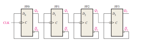
Figure 1 Logic diagram of a 4-bit asynchronous binary counter.
One way to make the counter recycle after the count of nine (1001) is to decode count ten (1010) with a NAND gate and connect the output of the NAND gate to the clear (CLR) inputs of the flip-flops. As a result, the counter recycles back to the 0000 state after the 1001 state.
In this way, 4-bit asynchronous counter can be modified into a decade counter (BCD Counter). Figure 1a shows the logic diagram of the decade counter. There is a minor modification of the basic 4-bit asynchronous counter circuit due to the partial decoding of count ten (1010) with a NAND gate.
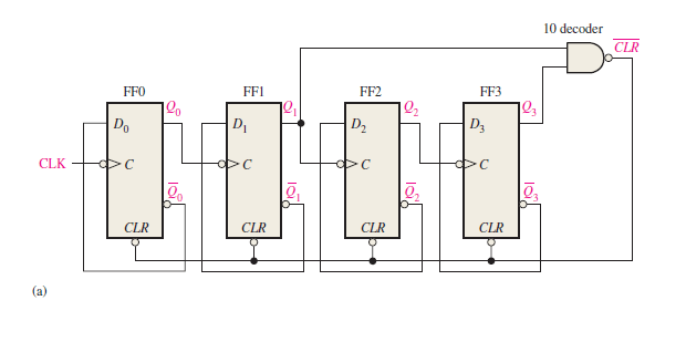
Figure 1(a) Logic diagram of asynchronous decade counter showing the partial decoding of count ten (1010) with a NAND gate.
What is partial decoding technique?
Notice in Figure 1(a) that only Q1 and Q3 are connected to the NAND gate inputs. This arrangement is an example of partial decoding, in which the two unique states (Q1 = 1 and Q3 = 1) are sufficient to decode the count of ten because none of the other states (zero through nine) have both Q1 and Q3 HIGH at the same time. When the counter goes into count ten (1010), the decoding gate output goes LOW and asynchronously resets (clear) all the flip-flops.
Timing diagram of asynchronous decade counter (BCD counter)
The resulting timing diagram is shown in Figure 1(b) . Notice that there is a glitch in the Q1 waveform.
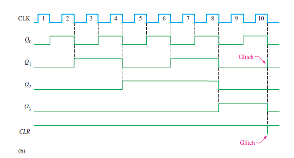
Figure 1(b) Timing diagram of an asynchronously clocked decade counter with asynchronous recycling.
The reason for this glitch is that Q1 must first go HIGH before the count of ten can be decoded. Not until several nanoseconds after the counter goes to the count of ten does the output of the decoding gate go LOW (both inputs are HIGH). Thus, the counter is in the 1010 state for a short time before it is reset to 0000, thus producing the glitch on Q1 and the resulting glitch on the CLR line that resets the counter.
Related posts (for further study) on Binary Counter
Asynchronous Counter – study & revision notes
Synchronous Counter – Study & Revision Notes
How to design a Synchronous counter – step by step guide
2-bit Synchronous Binary Counter using J-K flip-flops
A 3-Bit Asynchronous Binary Counter – Up Counter
Asynchronous Up counter for Positive & Negative edge-triggered flip-flops
Binary Counter Sequential Circuit – FAQs
Frequently Asked Questions on Flip-Flops Sequential Circuit
Numerical problems on asynchronous counter & synchronous counter
J-K flip-flop – Frequently asked questions for semester & GATE exam
Modulus-M (MOD-M) asynchronous counter – Study and revision notes
Digital Electronics – Hub page
Author of this post
This post is co-authored by Professor Saraswati Saha, who is an assistant professor at RCCIIT, a renowned degree engineering college in India. Professor Saha teaches subjects related to digital electronics & microprocessors.