
Numerical problems on asynchronous counter & synchronous counter
This post presents a bunch of numerical problems on the asynchronous counter (or ripple counter) & synchronous counter. You will get solutions to the problems as well. Students preparing for B.E./B.Tech semester examinations and GATE will find this post and the numerical problems useful.
Problem number 1
Problem statement:
Calculate the frequency of a 4-bit ripple counter, if the period of the waveform at the last flip-flop is 64 microseconds.
Answer:
In a 4-bit ripple counter, four flip-flops (FF0to FF3) are used. The input frequency of flip-flop FF0 is ‘f ‘and its output waveform frequency is f/2 which is applied as input of FF1. Consequently, the output waveform frequency of FF1 is f/4 which is used as input of FF2. Then output waveform frequency of FF2 is f/8 which is used as input of FF3. Therefore, the output waveform frequency of FF3 is f/16 and the time period is T=1/frequency=16/f.
Since the time period of the last flip-flop (FF3) is 64 microseconds,
T=16/f=64 x 10-6,
Then clock frequency of a 4-bit ripple counter is ‘f’ =16/ (64 x 10-6) Hz=250 kHz.
Problem number 2
Problem statement:
A 4-bit asynchronous binary counter is shown in Figure (a) below. Each D flip-flop is negative edge-triggered and has a propagation delay for 10 nanoseconds (ns). Develop a timing diagram showing the Q output of each flip-flop, and determine the total propagation delay time from the triggering edge of a clock pulse until a corresponding change can occur in the state of Q3. Also, determine the maximum clock frequency at which the counter can be operated.
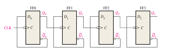
Figure (a): Logic diagram of 4-bit asynchronous binary counter using negative edge-triggered D flip-flop.
Answer:

Figure (b): Timing diagram of 4-bit asynchronous binary counter using negative edge-triggered D flip-flop.
The timing diagram with delays omitted is as shown in Figure (b).
For the total delay time, the effect of CLK16 must propagate through four flip-flops before Q3 changes,
So the total propagation delay time,
tp(tot) is = 4 * 10 ns = 40 ns.
The maximum clock frequency is,
fmax =1/tp(tot)
=1/40 ns = 25 MHz
The counter should be operated below this frequency to avoid problems due to the propagation delay.
Problem number 3
Problem statement:
If the input frequency on the left is 60 Hz, find out the output frequency from the modulo-6 counter. Also, find out the output frequency from the decade counter.
Solution :
Here is the diagram from which it is clear that the output frequency from the modulo-6 counter will be 60/6=10 Hz and this is the input clock frequency for the decade counter. So the output frequency from the decade counter is 10/10=1Hz.
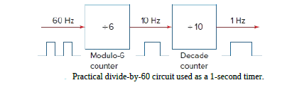
Practically decade counter followed by a modulo-6 counter is used as a divide-by-60 circuit and used as a 1-second timer.
Problem number 4
Problem statement:
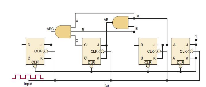
(a) Determine fmax for the synchronous counter of the Figure below, if tpd for each FF is 50 ns and tpd for each AND gate is 20 ns. Compare this value with fmax for a MOD-16 ripple counter.
(b) What must be done to convert this counter to MOD-32?
(c) Determine fmax for the MOD-32 parallel counter.
Solution
- (a) In a synchronous counter, the total delay that must be allowed between input clock pulses is equal to FF tpd + AND gate tpd. Thus, the period Tclock = 50 + 20 = 70 ns, and so the synchronous counter has a maximum frequency of fmax =1/T=1/70 ns = 14.3 MHz
A MOD-16 ripple counter uses four FFs with tpd = 50 ns.
From Equation, Tclock = N * tpd. Thus, fmax for the ripple counter is fmax =1/T=1/4 * 50 ns= 5 MHz
- (b) A fifth FF must be added because 25 = 32. The CLK input of this FF is also tied to the input pulses. Its J and K inputs are fed by the output of a four-input AND gate whose inputs are A, B, C, and D.
- (c) fmax is still determined as in (a) regardless of the number of FFs in the parallel counter (synchronous counter). Thus, fmax is still 14.3 MHz.
Related posts (for further study) on Binary Counter
Asynchronous Counter – study & revision notes
Synchronous Counter – Study & Revision Notes
How to design a Synchronous counter – step by step guide
2-bit Synchronous Binary Counter using J-K flip-flops
A 3-Bit Asynchronous Binary Counter – Up Counter
Asynchronous Up counter for Positive & Negative edge-triggered flip-flops
Binary Counter Sequential Circuit – FAQs
Frequently Asked Questions on Flip-Flops Sequential Circuit
Numerical problems on asynchronous counter & synchronous counter
J-K flip-flop – Frequently asked questions for semester & GATE exam
Modulus-M (MOD-M) asynchronous counter – Study and revision notes
Digital Electronics – Hub page
Author of this post
This post is co-authored by Professor Saraswati Saha, who is an assistant professor at RCCIIT, a renowned degree engineering college in India. Professor Saha teaches subjects related to digital electronics & microprocessors.