
JK flip flop
Last updated on June 29th, 2023 at 01:27 pm
In this post, we are going to cover the JK flip flop and discuss its operation, truth table, and excitation table. This post will help students to prepare for the semester & GATE examination.
JK flip flop truth table
The logic symbol and truth table of the J-K flip-flop are given in Figure 1.1.
This basic operation of a positive edge-triggered J-K flip-flop is illustrated in Figure 1.2.
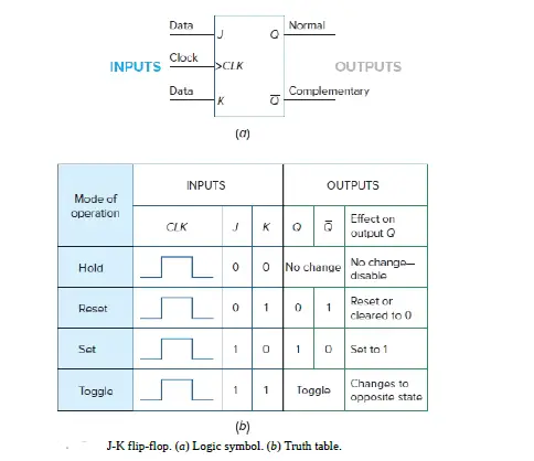
Figure 1.1 (a) Logic symbol and (b) Truth table of J-K flip-flop.
Operation of JK flip flop (explanation using truth table)
The J and K inputs of the J-K flip-flop are synchronous inputs because data on these inputs are transferred to the output of the flip-flop only on the triggering edge of the clock pulse.
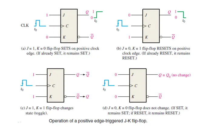
Figure 1.2 Operation of a positive edge-triggered J-K flip-flop
When J is HIGH and K is LOW, the Q output goes HIGH on the triggering edge of the clock pulse, and the flip-flop is SET.
When J is LOW and K is HIGH, the Q output goes LOW on the triggering edge of the clock pulse, and the flip-flop is RESET.
When both J and K are LOW, the output does not change from its prior state. This is called the No Change State (NC).
When J and K are both HIGH, the flip-flop changes state. This is called the toggle mode.
Remember, the flip-flop cannot change state except on the triggering edge of a clock pulse. The J and K inputs can be changed at any time when the clock input is LOW or HIGH (except for a very short interval around the triggering transition of the clock) without affecting the output.
We must review the operation of the J-K flip-flop using a different approach, one called an excitation table or transition table.
JK flip flop Excitation table | Transition table of JK flip flop
Here is the operation of the J-K flip-flop using a different approach, one called an excitation table (Table 1).
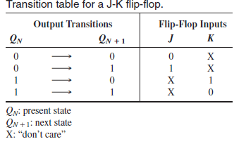
figure 1.3: J-K Excitation Table OR J-K Transition Table
The leftmost column of this table lists each possible FF output transition. This column lists the FF’s PRESENT state, symbolized as QN, and the NEXT state, symbolized as QN+1, for each transition. The last column list the J and K levels required to produce each transition. Let’s examine each case.
Operation of the JK flip flop (explanation using the Transition table or Excitation table)
0 to 0 transition: The FF PRESENT state is at 0 and is to remain at 0 when a clock pulse is applied. From our understanding of how a J-K flip-flop works, this can happen when either J = K = 0 (no-change condition) or J = 0 and K = 1 (clear condition). Thus, J must be at 0, but K can be at either level. The table indicates this with a “0” under J and an “x” under K. Recall that “x” means the don’t-care condition.
0 to 1 transition: The PRESENT state is 0 and is to change to a 1, which can happen when either J = 1 and K = 0 (set condition) or J = K = 1 (toggle condition). Thus, J must be a 1, but K can be at either level for this transition to occur.
1 to 0 transition: The PRESENT state is 1 and is to change to a 0, which can happen when either J = 0 and K = 1 or J = K = 1. Thus, K must be a 1, but J can be at either level.
1 to 1 transition: The PRESENT state is a 1 and is to remain a 1, which can happen when either J = K = 0 or J = 1 and K = 0. Thus, K must be a 0 while J can be at either level.
Use of JK transition table
The use of this JK transition table (figure 1.3 above) is a principal part of the synchronous counter design procedure.
Author of this post
This post is co-authored by Professor Saraswati Saha, who is an assistant professor at RCCIIT, a renowned degree engineering college in India. Professor Saha teaches subjects related to digital electronics & microprocessors.
Related posts (for further study) on Binary Counter
Asynchronous Counter – study & revision notes
Synchronous Counter – Study & Revision Notes
How to design a Synchronous counter – step by step guide
2-bit Synchronous Binary Counter using J-K flip-flops
A 3-Bit Asynchronous Binary Counter – Up Counter
Asynchronous Up counter for Positive & Negative edge-triggered flip-flops
Binary Counter Sequential Circuit – FAQs
Frequently Asked Questions on Flip-Flops Sequential Circuit
Numerical problems on asynchronous counter & synchronous counter
J-K flip-flop – Frequently asked questions for semester & GATE exam
Modulus-M (MOD-M) asynchronous counter – Study and revision notes