
2 bit Synchronous Counter using JK flip flops
Last updated on June 29th, 2023 at 03:23 pm
In this post, we will cover the Logic diagram, operation, & timing diagram of a 2-bit Synchronous Binary Counter using J-K flip-flops. In one of the earlier posts, we discussed How to design a Synchronous counter in a step-by-step guide.
Logic diagram of a 2 bit synchronous counter
Figure 1(a) shows a 2-bit synchronous binary counter. Notice that an arrangement different from that for the asynchronous counter must be used for the J1 and K1 inputs of FF1 in order to achieve a binary sequence.
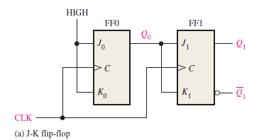
Figure 1(a): Logic diagram of a 2-bit synchronous binary counter
Operation of a 2 bit synchronous counter using J-K flip-flop
The operation of a J-K flip-flop synchronous counter is as follows: First, assume that the counter is initially in the binary 0 state; that is, both flip-flops are RESET.
When the positive edge of the first clock pulse is applied, FF0 will toggle and Q0 will therefore go HIGH.
What happens to FF1 at the positive-going edge of CLK1? To find out, let’s look at the input conditions of FF1. Inputs J1 and K1 are both LOW because Q0, to which they are connected, has not yet gone HIGH.
Remember, there is a propagation delay from the triggering edge of the clock pulse until the Q output actually makes a transition.
So, J = 0 and K = 0 when the leading edge of the first clock pulse is applied. This is a no-change condition, and therefore FF1 does not change state. A timing detail of this portion of the counter operation is shown in Figure 7(b).
Timing diagram of a 2 bit synchronous counter
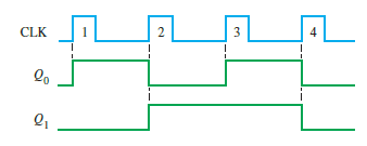
Figure 1(b) Timing diagram of a 2-bit synchronous binary counter
Counter output Table of a 2 bit synchronous counter
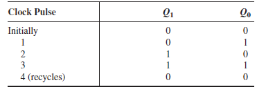
table 1: counter output table of a 2-bit synchronous binary counter
Summary
Since it goes through a binary sequence, the counter in Figure 1(a) is a binary counter. It actually counts the number of clock pulses up to three (22-1=3), and on the fourth pulse, it recycles to its original state (Q0 = 0, Q1=0).
The term recycle is commonly applied to counter operation; it refers to the transition of the counter from its final state back to its original state.
Related posts (for further study) on Binary Counter
Asynchronous Counter – study & revision notes
Synchronous Counter – Study & Revision Notes
How to design a Synchronous counter – step by step guide
2-bit Synchronous Binary Counter using J-K flip-flops
A 3-Bit Asynchronous Binary Counter – Up Counter
Asynchronous Up counter for Positive & Negative edge-triggered flip-flops
Binary Counter Sequential Circuit – FAQs
Frequently Asked Questions on Flip-Flops Sequential Circuit
Numerical problems on asynchronous counter & synchronous counter
J-K flip-flop – Frequently asked questions for semester & GATE exam
Modulus-M (MOD-M) asynchronous counter – Study and revision notes
Digital Electronics – Hub page
Author of this post
This post is co-authored by Professor Saraswati Saha, who is an assistant professor at RCCIIT, a renowned degree engineering college in India. Professor Saha teaches subjects related to digital electronics & microprocessors.