
Modulus-M (MOD-M) asynchronous counter – Study and revision notes
In this post, we will discuss the modulus-M (MOD-M) asynchronous counter and its design procedure.
What is a modulus-M (MOD-M) counter?
A modulus-M counter is a counter where M represents the number of states present in the counter. Here M <= 2n , where ‘n’ represents the number of flip-flops required to design the modulus-M counter.
For example, the modulus-6 counter has 6 states. Here the value of n is 3. That means 3 flip-flops are required to design the modulus-6 counter.
How to modify n-bit asynchronous binary counters to Mod-M counter using reset logic technique?
We know that n-bit asynchronous binary counters can count N clock pulses (i.e., number of states) where N = 2n, and n = Number of Flip-Flops.
For example, the 3-bit counter can count 8 clock pulses and has 8 different states (0 to 7). And this 3-bit counter is known as a MOD-8 counter.
To count M clock pulses which is less than N (N= 2n ), we need to take the help of a reset terminal (CLR) of the flip-flops. The combinational circuit is designed such that all the flip-flops can reset them after count M.
The block diagram of the Modulus-M counter is shown in Figure 1.
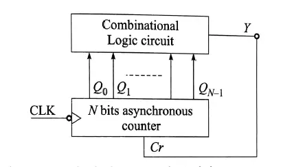
Figure1: Block diagram of Modulus-M asynchronous counter
The output (Y) of the combinational circuit must be zero (Y=0) to enable the CLR (reset) input of all the flip-flops (considering reset input is active LOW) to reset them after the M clock pulse.
Design procedure of a Modulus-M asynchronous counter
The procedure to design a Modulus-M asynchronous counter is as follows:
Step 1: Find the minimum number of flip-flops (n) required for the design, using the equation: 2n-1 <= M <=2n
Step 2: prepare the sequence and design the combinational circuit such that all the flip-flops are reset after the M clock pulse. Follow the following steps 2(a) and 2(b).
2(a) Draw the truth table of a ripple counter with the output of a combinational circuit Y, such that Y=1 for the valid state and Y=0 for the invalid state.
2(b) Draw the K-map for output Y and simplify.
For example, let us consider a MOD-6 counter. The minimum number of flip-flops (n) required is, M<2n or 6< 2n i.e. n=3 and the design of the combinational circuit will be such that all the flip-flops can reset after 6 clock pulses.
Related posts (for further study) on Binary Counter
Asynchronous Counter – study & revision notes
Synchronous Counter – Study & Revision Notes
How to design a Synchronous counter – step by step guide
2-bit Synchronous Binary Counter using J-K flip-flops
A 3-Bit Asynchronous Binary Counter – Up Counter
Asynchronous Up counter for Positive & Negative edge-triggered flip-flops
Binary Counter Sequential Circuit – FAQs
Frequently Asked Questions on Flip-Flops Sequential Circuit
Numerical problems on asynchronous counter & synchronous counter
J-K flip-flop – Frequently asked questions for semester & GATE exam
Modulus-M (MOD-M) asynchronous counter – Study and revision notes
Digital Electronics – Hub page
Author of this post
This post is co-authored by Professor Saraswati Saha, who is an assistant professor at RCCIIT, a renowned degree engineering college in India. Professor Saha teaches subjects related to digital electronics & microprocessors.