
Asynchronous inputs of the flip-flop – Preset & Clear
Last updated on May 14th, 2022 at 05:24 pm
In this post, we will know about Asynchronous inputs (or Preset & Clear inputs) of the flip-flop sequential circuit.
Asynchronous input versus Synchronous input of flip-flop
For the clocked flip-flops, the S, R, J, K, D, and T inputs are normally referred to as control inputs. These are also called synchronous inputs because their effect on the FF output is synchronized with the CLK input. As we have seen, the synchronous control inputs must be used in conjunction with a clock signal to trigger the FF.
Most clocked FFs also have one or more asynchronous inputs that operate independently of the synchronous inputs and clock input. These asynchronous inputs can be used to set the FF to the 1 state or clear (reset) the FF to the 0 state at any time, regardless of the conditions at the other inputs. Stated in another way, the asynchronous inputs are override inputs, which can be used to override all the other inputs in order to place the FF in one state or the other.
Preset & Clear input of flip-flop | Asynchronous inputs
Figure.1 shows a J-K flip-flop with two asynchronous inputs designated as PRESET and CLEAR. These are active-LOW inputs, as indicated by the bubbles on the FF symbol. The accompanying function table summarizes how they affect the FF output.
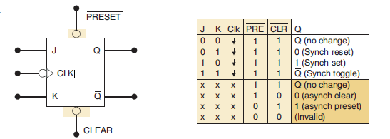
Figure 1: J-K flip-flop with two asynchronous inputs designated as PRESET and CLEAR
Let’s examine various cases from the function table above. (figure 1).
- PRESET = CLEAR = 1. The asynchronous inputs are inactive and the FF is free to respond to the J, K, and CLK inputs; in other words, the clocked operation can take place.
- PRESET = 0; CLEAR = 1. The PRESET is activated and Q is immediately set to 1 no matter what conditions are present at the J, K, and CLK inputs. The CLK input cannot affect the FF while PRESET = 0.
- PRESET = 1; CLEAR = 0. The CLEAR is activated and Q is immediately cleared to 0 independent of the conditions on the J, K, or CLK inputs. The CLK input has no effect while CLEAR = 0.
- PRESET = CLEAR = 0. This condition should not be used because it can result in an ambiguous response.
It is important to realize that these asynchronous inputs respond to dc levels. This means that if a constant 0 is held on the PRESET input, the FF will remain in the Q = 1 state regardless of what is occurring at the other inputs.
Similarly, a constant LOW on the CLEAR input holds the FF in the Q = 0 state. Thus, the asynchronous inputs can be used to hold the FF in a particular state for any desired interval.
Most often, however, the asynchronous inputs are used to set or clear the FF to the desired state by application of a momentary pulse.
Many clocked FFs that are available as ICs will have both of these asynchronous inputs; some will have only the CLEAR input. Some FFs will have asynchronous inputs that are active-HIGH rather than active-LOW. For these FFs the FF symbol would not have a bubble on the asynchronous inputs.
Activation of Preset & Clear input (asynchronous inputs)
Figure 2. shows the symbol for a J-K FF that responds to an NGT (Negative Edge Transition) on its clock input and has active-LOW asynchronous inputs. The external active-LOW asynchronous inputs are labeled PRE and CLR. The bubble on input means that the input responds to a logic LOW signal.
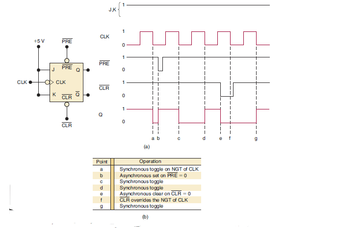
Figure. 2 The symbol for a J-K FF that responds to an NGT on its clock input and has active-LOW asynchronous inputs
Initially, PRE and CLR are in their inactive HIGH state, so that they will have no effect on Q. Thus, when the first NGT of the CLK signal occurs at point a, Q will toggle to its opposite state; remember, J = K = 1 produces the toggle operation.
At point b, the PRE input is pulsed to its active-LOW state. This will immediately set Q = 1. Note that PRE produces Q = 1 without waiting for an NGT at CLK. The asynchronous inputs operate independently of CLK.
At point c, the NGT of CLK will again cause Q to toggle to its opposite state. Note that PRE has returned to its inactive state prior to point c.
Likewise, the NGT of CLK at point d will toggle Q back HIGH.
At point e, the CLR input is pulsed to its active-LOW state and will immediately clear Q = 0. Again, it does this independently of CLK. The NGT of CLK at point f will not toggle Q because the CLR input is still active. The LOW at CLR overrides the CLK input and holds Q = 0.
When the NGT of CLK occurs at point g, it will toggle Q to the HIGH state because neither asynchronous input is active at that point.
Summary
Upon completion of this post, you will be able to
- distinguish between synchronous and asynchronous inputs.
- Preset & Clear inputs
- Activation of asynchronous inputs (preset & clear)
Related Post
J-K Flip-flop – Detailed Study Notes
Author of this post
This post is co-authored by Professor Saraswati Saha, who is an assistant professor at RCCIIT, a renowned degree engineering college in India. Professor Saha teaches subjects related to digital electronics & microprocessors.