
A 3-Bit Asynchronous Binary Counter in UP counting mode | Up Counter
In this post, we will discuss A 3-Bit Asynchronous Binary Counter in UP counting mode.
An asynchronous counter is one in which the flip-flops (FF) within the counter do not change states at exactly the same time because they do not have a common clock pulse.
In the next section, we will find what exactly the Up Counter is and how a 3-Bit Asynchronous Binary Counter operates in up-counting mode.
3-Bit Asynchronous binary Up counter
A 3-Bit Asynchronous Binary Counter in UP counting mode progresses through a binary count of zero (000) through seven (111) and then recycles to the zero (000) state. As the counting sequence is upward this counter is known as a 3-bit binary UP counter.
State sequence a 3-bit asynchronous binary UP counter
The state sequence for a 3-bit binary UP counter is listed in Table 1.
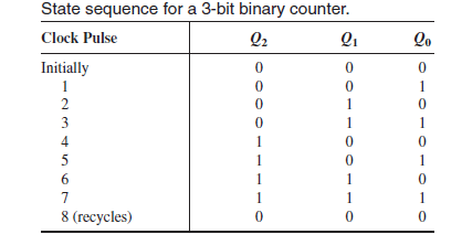
Table1: the state sequence for a 3-bit binary UP counter
Logic diagram & Timing diagram of 3-bit asynchronous binary UP counter
The logic diagram of the 3-bit asynchronous binary counter using D flip-flops is shown in Figure (1.1). The basic operation is the same as that of the 2-bit asynchronous binary counter except that the 3-bit counter has eight states, due to its three flip-flops.
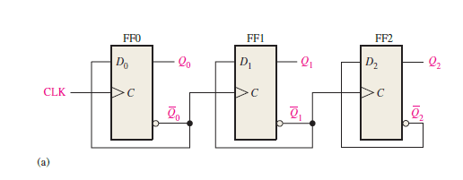
Figure1.1: Logic diagram of 3-bit asynchronous binary UP counter using the positive edge-triggered D F/Fs.
A timing diagram is also shown in Figure 1.2 for eight clock pulses.
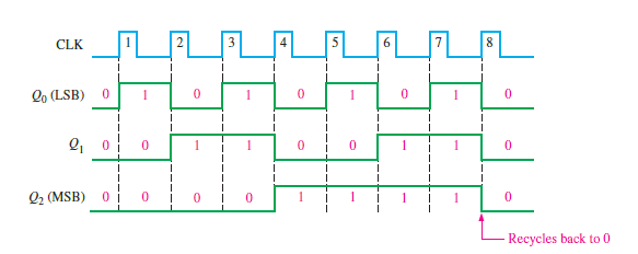
Figure1.2: Timing diagram of a 3-bit asynchronous binary UP counter for positive edge-triggered F/Fs.
How to expand this 3-bit counter for the higher count
This counter can be easily expanded for the higher count by connecting additional toggle flip-flops.
Design options – choice of flip-flops
For the designing of the asynchronous binary counter, we may use J-K flip-flop or T flip-flop, or D flip-flop in toggle mode.
Inputing flip-flops in toggle mode
You should remember the proper input conditions to operate the flip-flops in toggle mode for the particular one.
You can follow the tips given here to operate the flip-flops in toggle mode.
In toggle mode the inputs of the flip-flops should be like these: J=K=1 for J-K flip-flops, T=1 for T flip-flops, D=Q’ for D flip-flops.
Related posts (for further study) on Binary Counter
Asynchronous Counter – study & revision notes
Synchronous Counter – Study & Revision Notes
How to design a Synchronous counter – step by step guide
2-bit Synchronous Binary Counter using J-K flip-flops
A 3-Bit Asynchronous Binary Counter – Up Counter
Asynchronous Up counter for Positive & Negative edge-triggered flip-flops
Binary Counter Sequential Circuit – FAQs
Frequently Asked Questions on Flip-Flops Sequential Circuit
Numerical problems on asynchronous counter & synchronous counter
J-K flip-flop – Frequently asked questions for semester & GATE exam
Modulus-M (MOD-M) asynchronous counter – Study and revision notes
Digital Electronics – Hub page
Author of this post
This post is co-authored by Professor Saraswati Saha, who is an assistant professor at RCCIIT, a renowned degree engineering college in India. Professor Saha teaches subjects related to digital electronics & microprocessors.