
Asynchronous Counter
Last updated on June 30th, 2023 at 05:13 pm
This post presents a detailed study & revision notes on the Asynchronous Counter or ripple counter, the design of a 2-Bit Asynchronous Binary Counter with its Logic diagram, operation diagram & timing diagram.
In the Asynchronous Counter, the F/Fs are not clocked simultaneously. The output of the previous F/F becomes the clock input for the next F/F.
Why is the counter known as Asynchronous?
The term asynchronous refers to events that do not have a fixed time relationship with each other and, generally, do not occur at the same time. An asynchronous counter is one in which the flip-flops (FF) within the counter do not change states at exactly the same time because they do not have a common clock pulse.
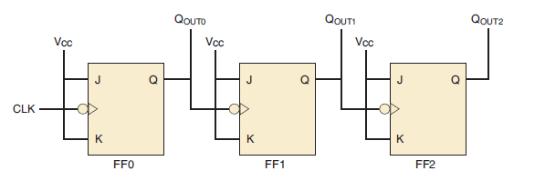
Figure 1 – The clock connection in the asynchronous counter
The above figure shows the clock connection in the asynchronous counter, where a 3-bit counter is connected for asynchronous operation.
Notice that the clock (CLK) is applied to the clock input (CLK) of only the first flip-flop, FF0, which is always the least significant bit (LSB). The second flip-flop, FF1, is triggered by the Q output of FF0.
FF0 changes state at the negative-going edge of each clock pulse, but FF1 changes only when triggered by a negative-going transition of the Q output of FF0. Because of the inherent propagation delay time through a flip-flop, a transition of the input clock pulse (CLK) and a transition of the Q output of FF0 can never occur at exactly the same time. Therefore, the two flip-flops are never simultaneously triggered, so the counter operation is asynchronous.
NOTE: The clock input of an asynchronous counter is always connected only to the LSB flip-flop.
Why is the Asynchronous counter known as the ripple counter?
Asynchronous counters are commonly referred to as ripple counters for the following reason: The effect of the input clock pulse is first “felt” by FF0. This effect cannot get to FF1 immediately because of the propagation delay through FF0 as shown in Figure 1.
Then there is a propagation delay through FF1 before FF2 can be triggered. Thus, the effect of an input clock pulse “ripples” through the counter, taking some time, due to propagation delays, to reach the last flip-flop. As the triggers move through the flip-flops like a ripple, it is called a ripple counter.
A 2-Bit Asynchronous Binary Counter
Designing of 2-Bit Asynchronous Binary Counter using D flip-flops: its logic diagram, operation, and timing diagram are explained below.
Logic diagram of 2-bit Asynchronous Counter
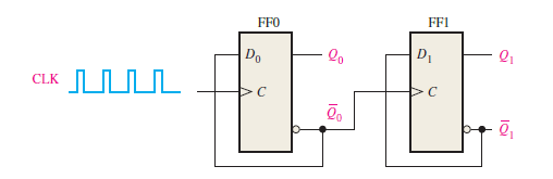
Figure 2 – Logic diagram of a 2-bit asynchronous counter using D flip-flops.
Figure 2 shows a 2-bit counter connected for asynchronous operation using D flip-flops.
Notice that the clock (CLK) is applied to the clock input (C) of only the first flip-flop, FF0, which is always the least significant bit (LSB). The second flip-flop, FF1, is triggered by the Q0 output of FF0. FF0 changes state at the positive-going edge of each clock pulse, but FF1 changes only when triggered by a positive-going transition of the Q0 output of FF0.
Because of the inherent propagation delay time through a flip-flop, a transition of the input clock pulse (CLK) and a transition of the Q0 output of FF0 can never occur at exactly the same time. Therefore, the two flip-flops are never simultaneously triggered, so the counter operation is asynchronous.
Note: Here 2 flip-flops are used for designing a 2-bit counter, if it is a 3-bit counter then 3 flip-flops will be used.
Operation and the Timing diagram of 2-bit Asynchronous counter
Let’s examine the basic operation of the asynchronous counter of Figure 2, by applying four clock pulses to FF0 and observing the Q output of each flip-flop.
Figure 3 illustrates the changes in the state of the flip-flop outputs in response to the clock pulses. Both flip-flops are connected for toggle operation (D = Q‘) and are assumed to be initially RESET (Q LOW and Q’ HIGH).
- The positive-going edge of CLK1 (clock pulse 1) causes the Q0 output of FF0 to go HIGH, as shown in Figure-3. At the same time the Q0’ (complement output) output goes LOW, but it has no effect on FF1 because a positive-going transition (Low to High) must occur to trigger the flip-flop. After the leading edge of CLK1, Q0 = 1 and Q1 =0 i.e. counter output 01
- The positive-going edge of CLK2 causes Q0 to go LOW. Output Q0’ goes HIGH and triggers FF1, causing Q1 to go HIGH. After the leading edge of CLK2, Q0 = 0 and Q1 = 1 i.e. counter output 10
- The positive-going edge of CLK3 causes Q0 to go HIGH again. Output Q0’ goes LOW and has no effect on FF1. Thus, after the leading edge of CLK3, Q0 = 1 and Q1 = 1 i.e. counter output 11.
- The positive-going edge of CLK4 causes Q0 to go LOW, while Q0’ goes HIGH and triggers FF1, causing Q1 to go LOW. After the leading edge of CLK4, Q0 = 0 and Q1 = 0 i.e. counter output 00. The counter has now recycled to its original state (both flip-flops are RESET).
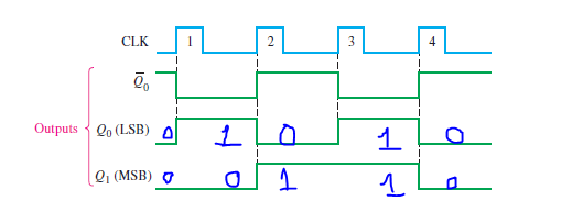
Figure 3 – Timing diagram of 2-bit Asynchronous counter
In the timing diagram, the waveforms of the Q0 and Q1 outputs are shown relative to the clock pulses as illustrated in Figure 3. For simplicity, the transitions of Q0, Q1, and the clock pulses are shown as simultaneous even though this is an asynchronous counter. There is, of course, some small delay between the CLK and the Q0 transition and between the Q0 transition and the Q1 transition.
Note in Figure 3 that the 2-bit counter exhibits four different states, as you would expect with two flip-flops (22=4). Also, notice that if Q0 represents the least significant bit (LSB) and Q1 represents the most significant bit (MSB), the sequence of counter states represents a sequence of binary numbers as listed in the table below:
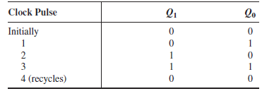
Since it goes through a binary sequence, the counter in Figure 2 is a binary counter. It actually counts the number of clock pulses up to three (22-1=3), and on the fourth pulse, it recycles to its original state (Q0 = 0, Q1=0).
The term recycle is commonly applied to counter operation; it refers to the transition of the counter from its final state back to its original state.
Related Study
Synchronous Counter – revision notes
Author of this post
This post is co-authored by Professor S. Saha, who is an assistant professor in a renowned degree engineering college in India. Professor Saha teaches subjects related to digital electronics & microprocessors.