
Propagation Delay in Ripple Counters: Study notes & Numerical problem
In this post, we will study the Propagation Delay in Ripple Counters. We will also solve a sample Numerical problem to illustrate the effect of propagation delays in a 4-bit asynchronous binary counter.
Propagation Delay in Ripple Counters – explained
Ripple counters are the simplest type of binary counters because they require the fewest components to produce a given counting operation.
They have one major drawback, which is caused by their basic principle of operation. Each FF is triggered by the transition at the output of the preceding FF, as shown in Figure.1
We know that asynchronous counters are commonly referred to as ripple counters. In ripple counters, the effect of the input clock pulse is first “felt” by FF0. This effect cannot get to FF1 immediately because of the propagation delay time tpd through FF0. Then there is the propagation delay through FF1 before FF2 can be triggered. Thus, the effect of an input clock pulse “ripples” through the counter, taking some time, due to propagation delays, to reach the last flip-flop.
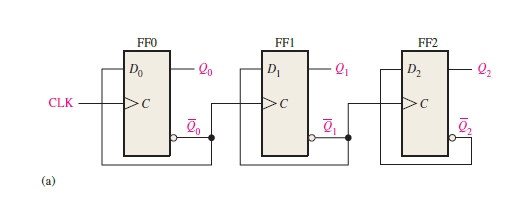
Figure.1 Logic diagram of a 3-bit asynchronous (ripple-clocked) binary counter.
This means that the second FF will not respond until a time tpd after the first FF receives an active clock transition; the third FF will not respond until a time equal to 2 * tpd after that clock transition; and so on. In other words, the propagation delays of the FFs accumulate so that the Nth FF cannot change states until a time equal to N * tpd after the clock transition occurs. This is illustrated in Figure.2, where the waveforms for a 3-bit asynchronous (ripple-clocked) counter are shown.
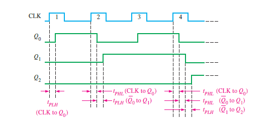
Figure.2 Propagation delays in a 3-bit asynchronous (ripple-clocked) binary counter.
Effect of propagation delays in a 3-bit asynchronous (ripple-clocked) binary counter
Notice that all the three flip-flops in the counter of Figure.1 change state on the leading edge of the fourth clock pulse, CLK4. This ripple clocking effect is shown in Figure.2 for the first four clock pulses, with the propagation delays indicated.
The LOW-to-HIGH transition of Q0 occurs one delay time (tPLH) after the positive-going transition of the input clock pulse.
The LOW-to-HIGH transition of Q1 occurs one delay time (tPLH) after the positive-going transition of Q0.
The LOW-to-HIGH transition of Q2 occurs one delay time (tPLH) after the positive-going transition of Q1.
As you can see, FF2 is not triggered until two delay times after the positive-going edge of the 4th clock pulse ( CLK4).
Thus, it takes three propagation delay times for the effect of the 4th clock pulse (CLK4), to ripple through the counter and change Q2 from LOW to HIGH.
This cumulative delay of an asynchronous counter is a major disadvantage in many applications because it limits the rate at which the counter can be clocked and creates decoding problems.
The maximum cumulative delay (N * tpd ) in a counter must be less than the period of the clock waveform (Tclock).
That is, for the proper counter operation we need,
Tclock >= N * tpd , where N = the number of FFs.
i.e., 1/fclock >= N * tpd or 1/ N * tpd >= fclock
Thus, fclock should be less than or equal to 1/ N * tpd.
Stated in terms of input-clock frequency, the maximum frequency that can be used in an asynchronous counter is given by,
fmax =1/N * tpd
For example, a 3-bit ripple counter having FFs with identical tpd = 50 ns will have a maximum input frequency
Limit of fmax =1/3 * 50 ns= 6.67 MHz.
Summary note:
We have found out that, as the number of FFs in the ripple counter increases, the total delay will increase and fmax will be lower.
Also will be able to determine the maximum operating frequency based on the number of FFs and propagation delays.
Numerical problem illustrating the effect of propagation delays in a 4-bit asynchronous binary counter
The following numerical problem will illustrate the effect of propagation delays in a 4-bit asynchronous binary counter.
A 4-bit asynchronous binary counter is shown in Figure.3a each D flip-flop is negative edge-triggered and has a propagation delay for 10 nanoseconds (ns). Develop a timing diagram showing the Q output of each flip-flop, and determine the total propagation delay time from the triggering edge of a clock pulse until a corresponding change can occur in the state of Q3. Also, determine the maximum clock frequency at which the counter can be operated.
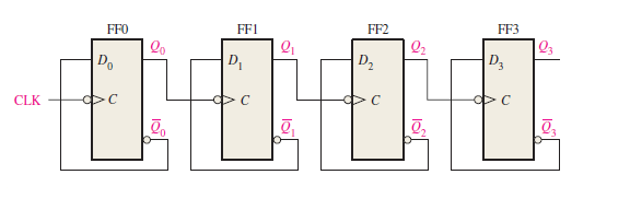
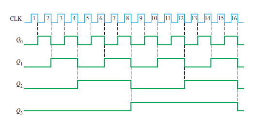
Figure 3b: 4-bit asynchronous binary counter timing diagram
Solution:
The timing diagram with delays omitted is as shown in Figure.3b.
For the total delay time, the effect of CLK16 must propagate through four flip-flops before Q3 changes, so
the total propagation delay time , tp(tot) = 4 * 10 ns = 40 ns
The maximum clock frequency is,
fmax =1/tp(tot)
=1/40 ns = 25 MHz
The counter should be operated below this frequency to avoid problems due to the propagation delay.
Related Posts
A 3-Bit Asynchronous Binary Counter in UP counting mode | Up Counter
Digital Electronics – Hub of posts
Author of this post
This post is co-authored by Professor Saraswati Saha, who is an assistant professor at RCCIIT, a renowned degree engineering college in India. Professor Saha teaches subjects related to digital electronics & microprocessors.