
Design steps of 4-bit asynchronous up counter using J-K flip-flop
In this post, we will discuss the Design steps of the 4-bit asynchronous up counter using J-K flip-flops.
In a binary counter, if flip-flops do not change states in exact synchronism with the applied clock pulses then the counter is called asynchronous binary counter. In this counter, each FF output drives the CLK input of the next FF.
To design a 4-bit asynchronous binary counter circuit four J-K flip-flops are required.
Design steps and the circuit analysis of 4-bit asynchronous up counter using J-K flip-flop
- The clock pulses are applied only to the CLK input of flip-flop A. Thus, flip-flop A will toggle (change to its opposite state) each time the clock pulses make a negative (HIGH-to-LOW) transition. Note that J = K=1 for all FFs.
- The normal output of flip-flop A acts as the CLK input for flip-flop B, and so flip-flop B will toggle each time the A output goes from 1 to 0. Similarly, flip-flop C will toggle when output B goes from 1 to 0, and flip flop D will toggle when output C goes from 1 to 0.
- FF outputs D, C, B, and A represent a four-bit binary number, with D as the MSB. Let’s assume that all FFs have been cleared to the 0 state (CLEAR inputs are not shown). The waveforms in Figure 1 show that a binary counting sequence from 0000 to 1111 is followed as clock pulses are continuously applied.
- After the negative (HIGH-to-LOW) transition of the 15th clock pulse has occurred, the counter FFs are in the 1111 condition. On the 16th negative (HIGH-to-LOW) transition, flip-flop A goes from 1 to 0, which causes flip-flop B to go from 1 to 0, and so on, until the counter is in the 0000 state. In other words, the counter has gone through one complete cycle (0000 through 1111) and has recycled back to 0000(as shown in timing diagram). From this point, it will begin a new counting cycle as subsequent clock pulses are applied.
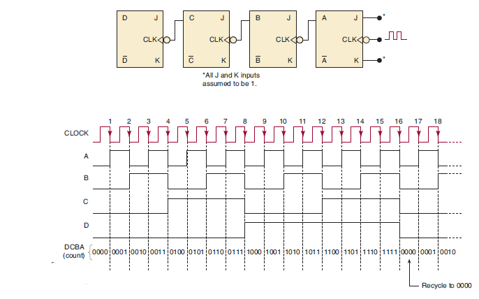
Figure 1: Logic diagram (upper one) and timing diagram (below one) of 4-bit asynchronous counter in up counting mode using J-K flip-flop.
From the logic diagram, it is clear that in this counter each FF output drives the CLK input of the next FF. This type of counter arrangement is called an asynchronous counter because the FFs do not change states in exact
synchronism with the applied clock pulses; only flip-flop A responds to the clock pulses. FF B must wait for FF A to change states before it can toggle; FF C must wait for FF B, and so on. Thus, there is a delay between the responses of successive FFs.
This type of counter is also often referred to as a ripple counter because of the way the FFs respond one after another in a kind of rippling effect. We will use the terms asynchronous counter and ripple counter interchangeably.
The 4-bit asynchronous counter in Figure.1 has 16 distinctly different states (0000 through 1111). Thus, it is a MOD-16 ripple counter. Recall that the MOD number is generally equal to the number of states that the counter goes through in each complete cycle before it recycles back to its starting state. Also, the counter counts upwards (0 to 15) and is known as up counter.
Frequency Division in asynchronous counter
We saw that in the basic counter each FF provides an output waveform that is exactly half the frequency of the waveform at its CLK input. To illustrate, suppose that the clock signal in Figure 1 (logic diagram) is 16 kHz.
Figure 1 (Timing diagram) shows the FF output waveforms. The waveform at output A is an 8-kHz square wave, at output B it is 4 kHz, at output C it is 2 kHz, and at output D it is 1 kHz. Notice that the output of flip-flop D has a frequency equal to the original clock frequency divided by 16.
In general, in any counter, the signal at the output of the last FF (i.e., the MSB) will have a frequency equal to the input clock frequency divided by the MOD number of the counter. For example, in a MOD-16 counter, the output from the last FF will have a frequency of 1/16 of the input clock frequency. Thus, it can also be called a divide-by-16 counter.