
Asynchronous Up counter for Positive & Negative edge-triggered flip-flops
In this post, we will discuss the following topics: (a) Asynchronous Up counter for Positive edge-triggered flip-flops & (b) Asynchronous Up counter for Negative edge-triggered flip-flops. For both of these, we will refer to the Logic diagram, Timing diagram, and operational details of the counter.
Asynchronous Up counter for Positive edge-triggered flip-flops
In this section, we will discuss the Logic diagram, Timing diagram, and operation of the Asynchronous Up counter for Positive edge-triggered flip-flops.
Logic diagram
Figure (1.1) shows the logic diagram of the Asynchronous Up counter for Positive edge-triggered flip-flops.
In the figure below, you can see the arrangement of a clock signal for the asynchronous Up counter when the flip-flops are positive edge triggered.
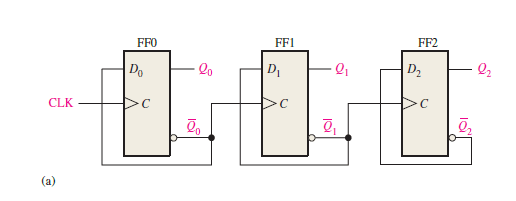
Figure 1.1: Logic diagram of 3-bit asynchronous binary Up counter using the positive edge-triggered D F/Fs.
Timing diagram & Circuit Operation
Now, let’s discuss the circuit operation and timing diagram of the Asynchronous Up counter for Positive edge-triggered flip-flops.
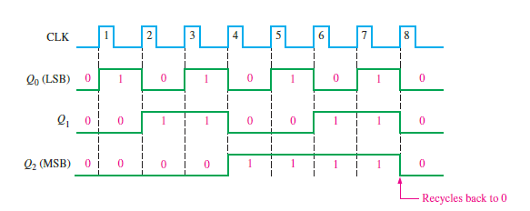
From the above timing diagram (figure 1.2) it is clear that this 3-bit asynchronous counter counts upwards.
The output Q0 (LSB) changes its state (toggle) at each positive transition of the clock.
The output Q1 changes state (toggle) every time Q0 goes from HIGH to LOW, i.e. when Q0’ goes from LOW to HIGH (as Q0’ acts as the clock input for FF1).
Q2 (MSB) changes state (toggle) each time Q1 goes from HIGH to LOW, i.e. when Q1’ goes from LOW to HIGH (because Q1’ acts as the clock input for FF2).
Thus, in an Up counter, each flip-flop, except the LSB flip-flop, must toggle when the inverted output (Q’) of the preceding flip-flop goes from LOW to HIGH; this is clearly illustrated in figure 1.2
Also observe that, as the D flip-flops are positive edge sensitive, the inverted output (Q’) of the preceding flip-flop acts as the clock input signal for the next flip-flop and so on. In this clock arrangement (figure 1.1) the counter counts upwards and is known as the Up counter.
Asynchronous Up counter for Negative edge-triggered flip-flops
In this section, we will discuss the Logic diagram, Timing diagram, and operation of the Asynchronous Up counter for Negative edge-triggered flip-flops.
Logic diagram
Figure (2.1) shows the logic diagram of the Asynchronous Up counter for negative edge-triggered flip-flops.
In the figure below, you can see the arrangement of a clock signal for the asynchronous Up counter when the flip-flops are negative edge triggered.
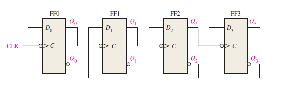
Figure2.1: Logic diagram of 4-bit asynchronous binary Up counter using the negative edge-triggered D F/Fs.
Timing diagram & Circuit Operation
Now, let’s discuss the circuit operation and timing diagram of the Asynchronous Up counter for Negative edge-triggered flip-flops.
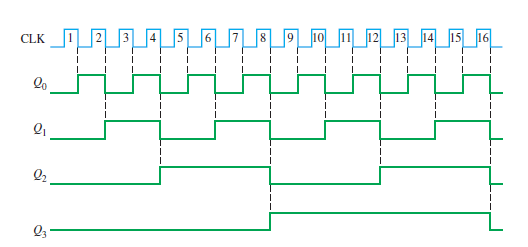
Figure2.2: Timing diagram of 4-bit asynchronous binary Up counter for negative edge triggered F/Fs.
From the above timing diagram (figure 2.2) it is clear that this 4-bit asynchronous counter counts upwards.
The output Q0 (LSB) changes its state (toggle) at each negative transition of the clock.
The output Q1 changes state (toggle) every time Q0 goes from HIGH to LOW because Q0 acts as the clock input for FF1.
Q2 changes state (toggle) each time Q1 goes from HIGH to LOW as Q1 acts as the clock input for FF2.
And Q3 (MSB) changes state (toggle) each time Q2 goes from HIGH to LOW, as Q2 acts as the clock input for FF3.
Thus, in the Up counter, each flip-flop, except the LSB flip-flop, must toggle when the output (Q) of the preceding flip-flop goes from HIGH to LOW; this is clearly illustrated in figure 2.2
Also observe that, as the D flip-flops are negative edge-sensitive, the output (Q) of the preceding flip-flop acts as the clock input signal for the next flip-flop and so on. In this clock arrangement (figure 2.1) the counter counts upwards and is known as the Up counter.
Related posts (for further study) on Binary Counter
Asynchronous Counter – study & revision notes
Synchronous Counter – Study & Revision Notes
How to design a Synchronous counter – step by step guide
2-bit Synchronous Binary Counter using J-K flip-flops
A 3-Bit Asynchronous Binary Counter – Up Counter
Asynchronous Up counter for Positive & Negative edge-triggered flip-flops
Binary Counter Sequential Circuit – FAQs
Frequently Asked Questions on Flip-Flops Sequential Circuit
Numerical problems on asynchronous counter & synchronous counter
J-K flip-flop – Frequently asked questions for semester & GATE exam
Modulus-M (MOD-M) asynchronous counter – Study and revision notes
Digital Electronics – Hub page
Author of this post
This post is co-authored by Professor Saraswati Saha, who is an assistant professor at RCCIIT, a renowned degree engineering college in India. Professor Saha teaches subjects related to digital electronics & microprocessors.