
Race Around Condition in JK Flip Flop
Last updated on June 29th, 2023 at 04:52 pm
In this post, we will study the Race Around Condition in JK flip flop. But before that, we will study the Logic symbol, truth table, operation of Positive-edge triggered JK flip-flop, and the JK Excitation Table or JK Transition Table. Finally we will find how to avoid the race around condition in JK flip flop.
Logic symbol & truth table of Positive-edge triggered JK flip flop
The J-K flip-flop has the features of all the other types of flip-flops. The logic symbol for the positive-edge triggered J-K flip-flop is illustrated in Fig.1.1(a). The inputs labeled J and K are the data inputs. The input labeled CLK is the clock input. Outputs Q and Q’ are the usual normal and complementary outputs on a flip-flop.
A truth table for the J-K flip-flop is shown in Fig.1.1(b).
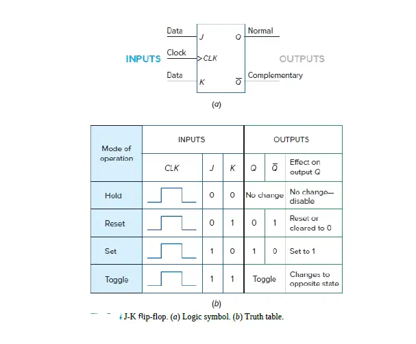
Figure 1.1 Positive-edge triggered J-K flip-flop (a) Logic symbol (b) Truth table
When the J and K inputs are both 0, the flip-flop is in the hold mode. In the hold mode, the data inputs have no effect on the outputs.
The outputs “hold” the last data present. Lines 2 and 3 of the truth table show the reset and set conditions for the Q output. Line 4 illustrates the useful toggle position of the J-K flip-flop.
When both data inputs J and K are at 1, repeated clock pulses cause the output to turn off-on-off-on-off-on, and so forth. This OFF-ON action is like a toggle switch and is called toggling.
Operation of the Positive-edge triggered J-K flip-flop
The basic operation of a positive edge-triggered J-K flip-flop is illustrated in Figure1.2
The J and K inputs of the J-K flip-flop are synchronous inputs because data on these inputs are transferred to the flip-flop’s output only on the triggering edge of the clock pulse.
When J is HIGH and K is LOW, the Q output goes HIGH on the triggering edge of the clock pulse, and the flip-flop is SET.
When J is LOW and K is HIGH, the Q output goes LOW on the triggering edge of the clock pulse, and the flip-flop is RESET.
When both J and K are LOW, the output does not change from its prior state. This is called the No Change state (NC).
When J and K are both HIGH, the flip-flop changes state. This is called the toggle mode.
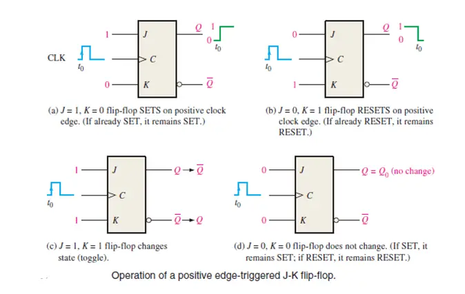
Figure 1.2 Operation of a positive edge-triggered J-K flip-flop.
Remember, the flip-flop cannot change state except on the triggering edge of a clock pulse. The J and K inputs can be changed at any time when the clock input is LOW or HIGH (except for a very short interval around the triggering transition of the clock) without affecting the output.
We must review the operation of the J-K flip-flop using a different approach, one called an excitation table or transition table.
JK Excitation Table | JK Transition Table
Here is the operation of the J-K flip-flop using a different approach, one called an excitation table (Table 1). The leftmost column of this table lists each possible FF output transition.
This column lists the FF’s PRESENT state, symbolized as QN, and the NEXT state, symbolized as QN+1, for each transition. The last column list the J and K levels required to produce each transition. Let’s examine each case.
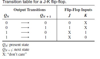
Table 1: J-K Excitation Table OR J-K Transition Table
The operation of the J-K flip-flop using the Transition table is explained below:
0 to 0 transition: The FF PRESENT state is at 0 and is to remain at 0 when a clock pulse is applied. From our understanding of how a J-K flip-flop works, this can happen when either J = K = 0 (no-change condition) or J = 0 and K = 1 (clear condition). Thus, J must be at 0, but K can be at either level. The table indicates this with a “0” under J and an “x” under K. Recall that “x” means the don’t-care condition.
0 to 1 transition: The PRESENT state is 0 and is to change to a 1, which can happen when either J = 1 and K = 0 (set condition) or J = K = 1 (toggle condition). Thus, J must be a 1, but K can be at either level for this transition to occur.
1 to 0 transition: The PRESENT state is 1 and is to change to a 0, which can happen when either J = 0 and K = 1 or J = K = 1. Thus, K must be a 1, but J can be at either level.
1 to 1 transition: The PRESENT state is a 1 and is to remain a 1, which can happen when either J = K = 0 or J = 1 and K = 0. Thus, K must be a 0 while J can be at either level.
The use of this J-K transition table (Table 1) is a principal part of the synchronous counter design procedure.
Race Around Condition in JK flip flop
The Race-around Condition is a major problem in clocked JK flip flop.
The truth table of the JK flip flop shows that when both data inputs J and K are at 1, and CLK=1 the output toggles.
Consider the input J=1 and K=1 and output Q=0; after the propagation delay of the flip flop, the output will change from 0 to 1. Since in a J-K flip-flop, the output is connected to inputs, this output act as input, and after the next propagation delay, the output will change from 1 to 0. This process is continued and at the end of the applied clock pulse, the output is uncertain. This situation is known as the Race-around Condition.
This uncertainty of output can be avoided if the propagation delay time of flip-flop (∆ t) is increased.
The propagation delay time of the flip-flop (∆ t) must be greater than the duration of the clock pulse (T). The duration of the applied clock pulse (T) is reduced and it becomes less than the propagation delay time of the flip-flop (∆ t). This is a restrictive requirement since the operation of the circuit depends on the width of the clock pulse.
Increasing the delay of the flip-flop is not a good solution. By increasing the delay, the speed of the system is decreased. It is also difficult to reduce the width of the applied pulse beyond the delay of the flip flop because the propagation delay time of the flip flop (∆ t) is in nanoseconds.
How to avoid Race Around condition in JK flip flop?
The most practical solution to avoid Race Around Condition in JK flip flop is
- to use the clocked J-K flip-flop in Master-and-Slave mode or
- to use edge-triggered J-K flip-flops
Related Posts
JK Flip-flop – operation, truth table, excitation table
Asynchronous inputs in Flip-Flops
Author of this post
This post is co-authored by Professor Saraswati Saha, who is an assistant professor at RCCIIT, a renowned degree engineering college in India. Professor Saha teaches subjects related to digital electronics & microprocessors.