
Design steps of 4-bit (MOD-16) synchronous up counter using J-K flip-flop
Last updated on December 8th, 2021 at 05:32 pm
In this post, we will discuss the Design steps of the 4-bit (MOD-16) synchronous up counter using the J-K flip-flop. We will start off by answering a few related questions first.
- What is synchronous counter?
- What is up counter?
- Why is the 4-bit counter known as MOD-16 counter?
- Why are we going for synchronous counter instead of asynchronous counter?
- Design steps of 4-bit synchronous counter (count-up) using J-K flip-flop
- Circuit Operation of a 4-bit ( MOD-16) synchronous counter
- The basic principle for constructing a synchronous counter can therefore be stated as follows
- Advantage of Synchronous Counters over Asynchronous Counters
- Related posts (for further study) on Binary Counter
What is synchronous counter?
In a synchronous counter, the clock input terminals of all flip-flops are commonly connected. Therefore, the same clock pulse simultaneously triggers all flip-flops of the counters.
What is up counter?
Synchronous binary counters can be able to count either in increasing or decreasing order. In a count-up mode, the counter value sequentially increased. For example, in a 3-bit up-counter the counting sequence is 0,1,2,3,4,5,6, and 7
Why is the 4-bit counter known as MOD-16 counter?
We know that n-bit synchronous counters can count N = 2n clock pulses, Where n = Number of Flip Flops. For example, a 4-bit counter has 24=16 different states (0 to 15) and is known as the MOD-16 counter.
Why are we going for synchronous counter instead of asynchronous counter?
The problems encountered with ripple counters are caused by the accumulated FF propagation delays. The FFs do not all change states simultaneously in sync with the input clock pulses.
These limitations can be overcome with the use of synchronous or parallel counters in which all of the FFs are triggered simultaneously (in parallel) by the clock input pulses.
Design steps of 4-bit synchronous counter (count-up) using J-K flip-flop
As the input clock pulses are applied to all the Flip-flops in a synchronous counter, some means must be used to control when an FF is to toggle and when it is to remain unaffected by a clock pulse. This is accomplished by using the J and K inputs and is illustrated in Figure1(c) for a 4-bit, MOD-16 synchronous counter.
If we see the circuit arrangement for this synchronous counter (Figure1(a)), we will find out the following points:
- The CLK inputs of all of the FFs are connected together so that the input clock signal is applied to each FF simultaneously.
- Only flip-flop A, the LSB, has its J and K inputs permanently at the HIGH level. The J, K inputs of the other FFs are driven by some combination of FF outputs.
- The synchronous counter requires more circuitry than does the asynchronous counter.
The counting sequence (Figure 1(a)) in a 4-bit up counter is 0,1,2,3,4,5,6, 7,…………,13,14,15,0. That is counter recycles after 16 clock pulses.
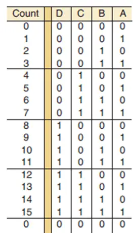
Figure 1(a): counting sequence in Synchronous MOD-16 counter.
Circuit Operation of a 4-bit ( MOD-16) synchronous counter
For a 4-bit ( MOD-16) synchronous counter circuit, to count properly on a given NGT (negative transition) of the clock, only those FFs that are supposed to toggle on that NGT should have J = K = 1. (figure 1(b))
Let’s look at the counting sequence in Figure1(a) to see what this means for each FF.
Case1:
The counting sequence shows that flip-flop A must change states at each NGT. For this reason, its J and K inputs are permanently HIGH so that it will toggle on each NGT of the clock input.
Case2:
The counting sequence shows that flip-flop B must change states on each NGT that occurs while A = 1.
For example, when the count is 0001, the next NGT must toggle B to the 1 state; when the count is 0011, the next NGT must toggle B to the 0 state; and so on. This operation is accomplished by connecting output A to the J and K inputs of flip-flop B so that J = K = 1 only when A = 1.
Case3:
The counting sequence shows that flip-flop C must change states on each NGT that occurs while A = B = 1. For example, when the count is 0011, the next NGT must toggle C to the 1 state; when the count is 0111, the next NGT
must toggle C to the 0 state; and so on. By connecting the logic signal AB to FF C’s J and K inputs, this FF will toggle only when A = B = 1.
Case4:
In a like manner, we can see that flip-flop D must toggle on each NGT that occurs while A = B = C = 1. When the count is 0111, the next NGT must toggle D to the 1 state; when the count is 1111, the next NGT must toggle D to the 0 state. By connecting the logic signal ABC to FF D’s J and K inputs, this FF will toggle only when A = B = C = 1.
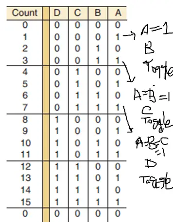
Figure 1(b) The basic principle for constructing a synchronous counter in up-counting mode.
The basic principle for constructing a synchronous counter can therefore be stated as follows
Each FF should have its J and K inputs connected so that they are HIGH only when the outputs of all lower-order FFs are in the HIGH state. Here is the logic diagram of 4-bit ( MOD-16) synchronous counter using J-K flip-flops (figure 1(c)).
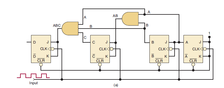
Figure 1(c): (MOD-16) Synchronous UP counter using J-K flip-flop. ( Each FF is clocked by the NGT of the clock input
signal so that all FF transitions occur at the same time).
And, here is the Timing diagram of the 4-bit (MOD-16) Synchronous UP counter using J-K flip-flop. ( Figure1(d) )
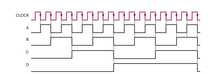
Figure1(d): Timing diagram of 4-bit (MOD-16) Synchronous UP counter using J-K flip-flop.
Advantage of Synchronous Counters over Asynchronous Counters
In a parallel counter, all of the FFs will change states simultaneously; that is, they are all synchronized to the NGTs of the input clock pulses. Thus, unlike the asynchronous counters, the propagation delays of the FFs do not add together to produce the overall delay. Instead, the total response time of a synchronous counter like the one in Figure1( c ) is the time it takes one FF to toggle (FF tpd ) plus the time for the new logic levels to propagate through a single AND gate(AND gate tpd ) to reach the J, K inputs.
That is, for a synchronous counter, total delay = FF tpd + AND gate tpd , where tpd is the propagation delay time.
This total delay is the same no matter how many FFs are in the counter, and it will generally be much lower than with an asynchronous counter with the same number of FFs. Thus, a synchronous counter can operate at a much higher input frequency. Of course, the circuitry of the synchronous counter is more complex than that of the asynchronous counter.
Related posts (for further study) on Binary Counter
Asynchronous Counter – study & revision notes
Synchronous Counter – Study & Revision Notes
How to design a Synchronous counter – step by step guide
2-bit Synchronous Binary Counter using J-K flip-flops
A 3-Bit Asynchronous Binary Counter – Up Counter
Asynchronous Up counter for Positive & Negative edge-triggered flip-flops
Binary Counter Sequential Circuit – FAQs
Frequently Asked Questions on Flip-Flops Sequential Circuit
Numerical problems on asynchronous counter & synchronous counter
J-K flip-flop – Frequently asked questions for semester & GATE exam
Modulus-M (MOD-M) asynchronous counter – Study and revision notes
Digital Electronics – Hub page
Author of this post
This post is co-authored by Professor Saraswati Saha, who is an assistant professor at RCCIIT, a renowned degree engineering college in India. Professor Saha teaches subjects related to digital electronics & microprocessors.