
Lockout condition in Counter with design to avoid it
In this post, we will discuss the Lockout condition and how to avoid it. We will also design a sequence generator to avoid lockout conditions.
What is Lockout Condition in a counter?
In a synchronous counter or sequence generator, if the counter or sequence generator finds itself in some unused state, the next state is unknown. It may be possible that the counter or sequence generator goes from one unused state to another unused state, but it never arrives at a used state. The synchronous circuit (counter or sequence generator) is then said to be in the “Lock Out” conditions.
The circuit that goes in lockout condition is called a bush less circuit. To make sure that the counter will come to the initial state from any unused state, the additional logic circuit is necessary.
How to avoid Lockout Condition in a counter?
To avoid lock-out conditions, there is a need to design the circuit in such a way when the counter or sequence generator is found itself in an unused state, the next state should be known and it must be a used state. This circuit will force the counter to go from an unused state to the next state as the initial state.
It is not always necessary to force all unused states into an initial state.
When the counter or sequence generator is found itself in an unused state, the next state should be the nearest used state.
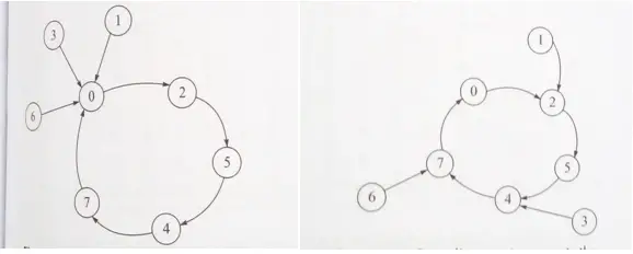
Fig 1: state diagram to generate the sequence 0-2-5-4-7-0 with lockout condition
From figure 1 above (left side), when the counter or sequence generator is found itself in an unused state, the next state is a used state 0.
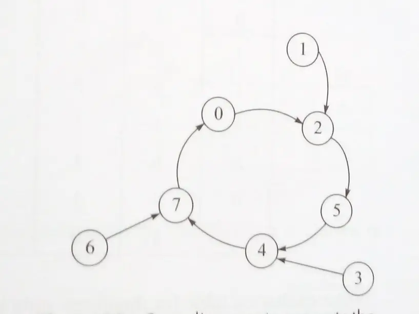
From figure 1 above (right side), when the counter or sequence generator is found itself in an unused state for example state 1, the next state is 2; and for the unused state 3, the next state is 4.
Design a sequence generator – considering lockout conditions
Problem statement: Design a sequence generator to generate the sequence 0->2->5->4->7->0 using J-K flip-flops and avoid the lockout condition.
Solution:
Step1: State diagram for the given sequence 0 ->2->5->4->7->0 is modified to consider the unused state for avoiding the lockout situation.
Step2: Use J-K flip-flops
Here, three J-K flip-flops are required because it is a 3-bit counter (output QCQBQA)
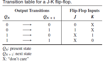
J-K Transition Table is given below:
Step 3: Draw the state table and the excitation table for the state diagram using J-K flip-flops.
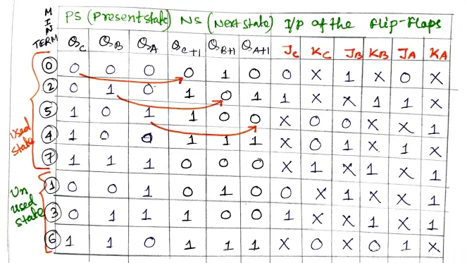
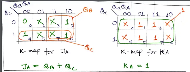
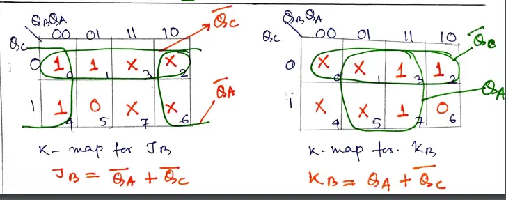
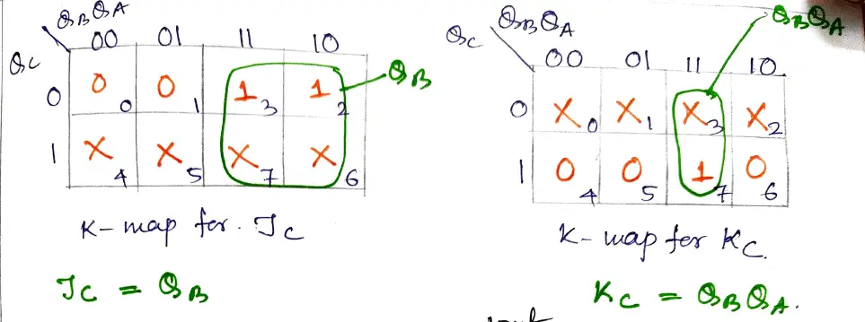
Step 4: Solve the K- map to get the reduced expression for each flip flop input. For the min-terms 0 to 7 get the output from the above table.
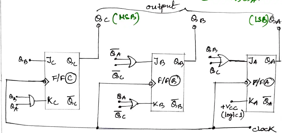
Step 5: implement the logic circuit with J-K flip-flop and logic gates.
Author of this post
This post is co-authored by Professor Saraswati Saha, who is an assistant professor at RCCIIT, a renowned degree engineering college in India. Professor Saha teaches subjects related to digital electronics & microprocessors.