
Four-input OR gate using two-input OR gates – How?
How would you hardware-implement a four-input OR gate using two-input OR gates only?
Solution
Figure 1 shows one possible arrangement of two-input OR gates that simulates a four-input OR gate. A, B, C and D are logic inputs and Y3 is the output. Figure 2 shows another possible arrangement.
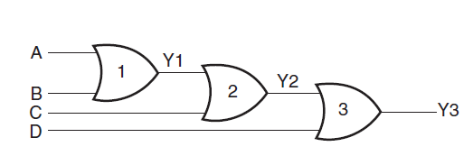
In the case of Fig. 1, the output of OR gate 1 is Y1 = (A+B). The second OR gate produces the output Y2 = (Y1+C)= (A+B+C). Similarly, the output of OR gate 3 is Y3 = (Y2+D)= (A+B+C+D).
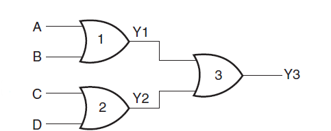
In the case of Fig. 2, the output of OR gate 1 is Y 1 = (A+B) The second OR gate produces the output Y 2 = (C+D). Output Y3 of the third OR gate is given by (Y1+Y2)= (A+B+C+D).