
4 to 2 Priority Encoder Design
Last updated on August 19th, 2023 at 04:46 pm
In this post, we will study the design procedure of a 4 to 2 Priority Encoder, step by step.
A priority encoder generates a binary code corresponding to the active input with the highest priority. So an encoder that includes the priority function for its operation is called a priority encoder.
The operation of the priority encoder is such that if two or more inputs are equal to 1 at the same time, the input having the highest priority will take precedence.
Design steps of four to two (4:2) Priority Encoder
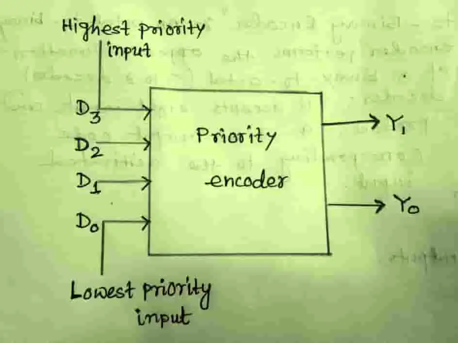
The block diagram for a four-input (4:2) priority encoder is given below.
From the diagram it is clear that the input D3 has the highest priority; so regardless of the values of the other inputs, when this input is 1, the output Y1 Y0 is 11 (i.e. 3).
D2 has the next priority level. The output is 10 if D2=1 and D3=0, irrespective of the values of the other two lower-priority inputs.
The output for D1 is generated only if higher priority inputs are 0, and so on down the priority level.
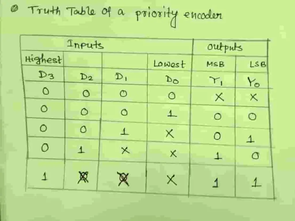
The truth table for a four-input (4:2) priority encoder is given in Table where X represents the don’t care state. For an input word, the active bit with the highest weight has priority and the output will be as per the highest priority input.
The next step is to solve the Karnaugh map for the output Y1 and Y0.
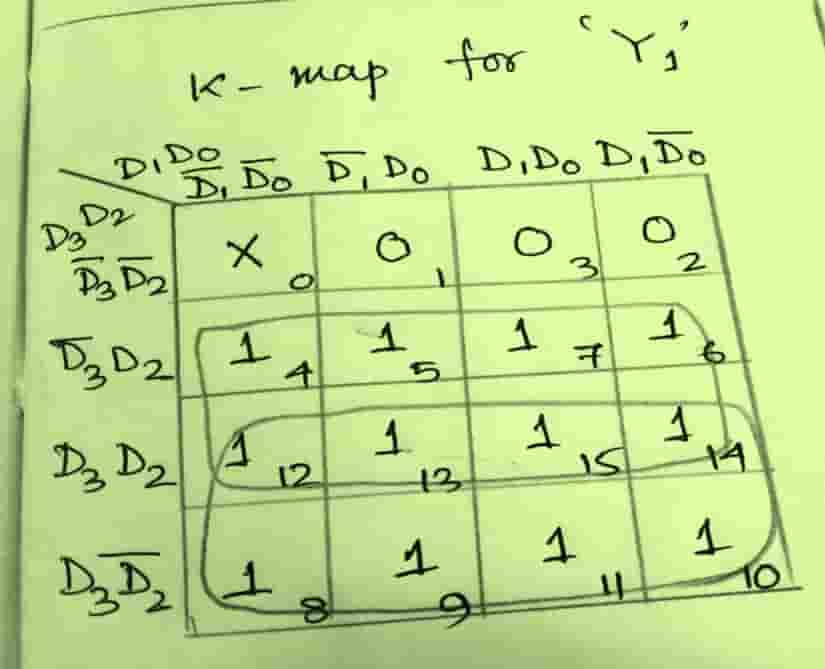
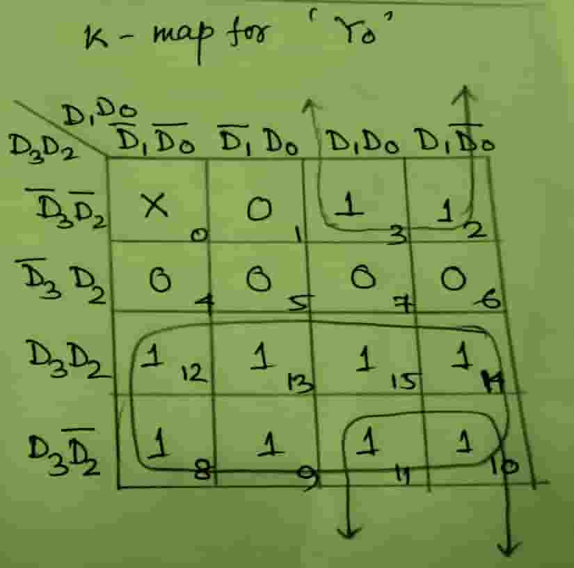
The minimized output equations can be written as follows:
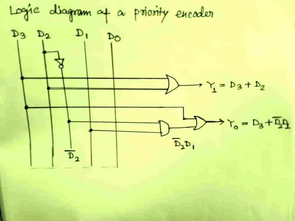
Y1 = D3 + D2
Y0 = D3 + D2’ D1
The logic circuit of the 4:2 priority encoder can then be realized as illustrated in Figure 4.
Application of priority encoder
The priority encoder is very useful in the following field.
- Keyboard encoder: when several keys are pressed simultaneously, only the key with the highest number is taken into consideration;
- Unit processing interrupt requests in a microprocessor: in case of simultaneous Interrupt requests, only the request with the highest priority is accepted.
Author of this post
This post is co-authored by Professor Saraswati Saha, who is an assistant professor at RCCIIT, a renowned degree engineering college in India. Professor Saha teaches subjects related to digital electronics & microprocessors.