
Flag Register of 8086
In this post, our topic of discussion is the Flag Register of 8086. We start with the fundamentals of flags and the flag register of a microprocessor. Then we present the flag register diagram of 8086 showing individual flag bits. The function of flag bits is discussed as well in this post. We also define and discuss status and control flags.
Flag Register of 8086 microprocessor
Flag register and flags in microprocessor
Each microprocessor has its own arithmetic and logic unit (ALU) that can perform computing functions. With the ALU the microprocessor architecture also includes the accumulator, the temporary register, and one flag register.
The temporary register is used to hold data during an arithmetic/logic operation. In most of these operations, the result is stored in the accumulator. The data conditions, after arithmetic and logic operations in the ALU, are reflected by setting or resetting the flip-flops called flags.
Therefore, the flags are the flip-flops and these are the parts of the register known as the Flag register or Program Status Word (PSW).
Flag register of the 8086 microprocessor – configuration of the 16-bit | Flag bit diagram of 8086 flag register
In the 8086 microprocessor, the flag register is 16-bit wide. Seven bits remain unused while the rest nine are used to indicate the conditions of flags.
The configuration of the 16-bit flag register of the 8086 microprocessor is shown below. Flag bits are also shown in the diagram.
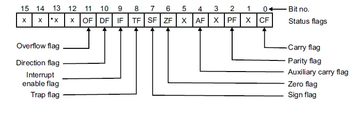
Figure: 8086 flag register configuration
Function of Flag Bits of 8086 Flag Register
Let’s discuss the functions of Flag bits of the 8086 flag register.
function of Bit-0 to Bit-7 of 8086 flag register
8 out of 16 flag bits of the 8086 microprocessor are 8085 compatible. The function of each such 8085 compatible flag bit (Bit-0 to Bit-7) of 8086 is listed in the table below.
| Bit No. | Name of the flag | Function |
| 0 | CF | Parity flag: This is an even parity flag. If the lower 8 bits of the result have an even number of 1s, it will be set to 1. Otherwise 0 for an odd number of 1s. |
| 1 | – | Auxiliary carry flag: It holds the carry after addition or borrows after subtraction of the bits in the bit position 3. Especially this flag is used by the instruction DAA or the DAS to adjust the value in AL after BCD addition or subtraction, respectively. |
| 2 | PF | The intel-reserved bit is normally set to zero. |
| 3 | – | The intel-reserved bit is normally set to zero. |
| 4 | AF | Zero flag: It indicates that the result of an arithmetic or logic operation is zero and the flag bit will be set to 1. Otherwise, 0 when the result is not zero. |
| 5 | – | The intel-reserved bit is normally set to zero. |
| 6 | ZF | Sign flag: It indicates the arithmetic sign of the result. If 0, the sign bit is zero and the result is positive. If 1, then sign bit is 1 and the result is negative. |
| 7 | SF | Sign flag: It indicates the arithmetic sign of the result. If 0, the sign bit is zero and the result is positive. If 1, then the sign bit is 1 and the result is negative. |
function of Bit-8 to Bit-15 of 8086 flag register
Trap Flag (TF) –Bit-8
This flag is used to debug a program. Setting the trap flag (i.e. TF=1) puts the microprocessor into a single-step mode for debugging. In single stepping, the 8086 microprocessor gets interrupted after the execution of each instruction and enters into single step ISR. If the trap flag is reset (i.e. TF=0), the trapping or debugging feature is disabled.
Interrupt Flag (IF) –Bit-9
This flag controls the operation of the INTR interrupt pin of the 8086. If the interrupt flag is set (i.e. IF=1), the microprocessor will recognize interrupt requests (INTR) from the peripherals. If the interrupt flag is reset (i.e. IF=0), the INTR pin is disabled and the microprocessor cannot recognize any interrupt requests and will ignore them. STI and CLI instructions are there in 8086 to set and clear the interrupt flag respectively.
Direction Flag (DF)–Bit-10
This flag is used to select the increment or decrement mode for the index register (SI and/or DI) during the execution of string instructions. If the direction flag is set (i.e. DF=1), the registers are automatically decremented and the access of string data will be from a higher memory location towards a lower memory location. If the directional flag is reset (i.e. DF=0), then access of the string data will be from the lower memory location towards the higher memory location. The index registers are automatically incremented. STD and CLD instructions are there in 8086 to set and clear the direction flag respectively.
Overflow flag (OF)-Bit-11
Signed negative numbers are represented in the 2’s complement form in the microprocessor. When signed numbers are added or subtracted, an overflow may occur. An overflow indicates that the result has exceeded the capacity of the machine. Normally in an 8-bit register, the minimum and maximum value of the signed number that can be stored is -128(=80H) and +127(=7EH), respectively. For operations on unsigned data, OF is ignored.
Intel-reserved bit-Bit-12 to Bit-15
Intel-reserved bit normally set to zero
Status and control flags in 8086 flag register
The 8086 flags in the flag register can be classified into status flags and control flags.
Status Flags in 8086 flag register
The flags CF (carry flag), PF (parity flag), AF (auxiliary carry flag), ZF (zero flag), SF (sign flag), and OF (overflow flag) are called status flags.
These flags indicate the status of the result that is obtained after the execution of an arithmetic or logic instruction.
Control Flags in 8086 flag register
The flags D (direction flag), I (interrupt flag), and T (trap flag) are called control flags, as they control the operation of the CPU.
Author of this post
This post is co-authored by Professor Saraswati Saha, who is an assistant professor at RCCIIT, a renowned degree engineering college in India. Professor Saha teaches subjects related to digital electronics & microprocessors.