
Interrupt Vector Table in 8086
In this post, we will understand the importance and table structure format of the interrupt vector table (IVT). It is a table in the memory that contains the interrupt vectors of different interrupts.
The interrupt vector is a four-byte entry in the IVT, which contains a 16-bit offset part and 16-bit segment base address part that are loaded in the IP (instruction pointer) and CS (code segment) registers, respectively, when an interrupt is received.
There are 256 interrupt types (Type 0 to Type 255) in the 8086 and the INT instruction (INT n, where n=0 to 255) of the 8086 can be used to generate any one of these possible interrupt types. These interrupts are called software interrupts.
Now, we will discuss how the 8086 does an indirect far jump to the start of the ISR (interrupt service subroutine) of the received interrupt.
When the 8086 responds to an interrupt, it refers to four memory locations present in the interrupt vector table (IVT), to get the new values of CS and IP. These memory locations are used to find the starting address of the ISR of the received interrupt in the memory.
In an 8086 system, the first 1 Kbyte (i.e. 1024 locations) of memory from the addresses 00000H to 003FFH is reserved for storing the starting addresses of interrupt service routines. This block of memory is often called the Interrupt Vector Table in 8086.
Since 4 bytes are required to store the CS (it can hold 2 bytes of base address) and IP (it can hold 2 bytes of offset) values for each interrupt service procedure, the table (containing 1024 byte locations) can hold the starting addresses for 256 interrupts (i.e. 256 X 4=1024) service routines.
When the 8086 processor responds to an interrupt, it goes to memory locations to get the CS and IP values for the start of the interrupt service routine. The 8086 gets the new values of the CS and IP register from four consecutive memory addresses. Figure 1 shows how the 256 interrupt pointers are arranged in the memory table.
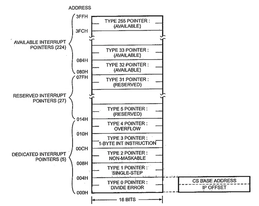
The above figure shows that the IP value is inserted as the lower-order word of the interrupt vector and the CS value is inserted as the higher-order word of the interrupt vector. Each interrupt vector is identified by a number called its ‘Type’, which is an 8-bit number. In 8086 the lowest five types (types 0-4) are dedicated to specific interrupts, types 5-31 are reserved by Intel, and the upper 224 interrupt types are available for the programmer.
Example: If the ISR of interrupt type 0 is stored in the memory starting at the address 30000H(i.e. 20-bit physical address), the segment part of the interrupt vector is entered as 3000H and its offset part is entered as 0000H in the IVT.
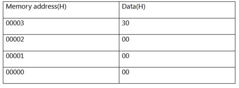
This is also clearly shown in the section on IVT, given below.
When these two values are loaded in the CS and IP registers, respectively, the 8086 calculates the address of the next instruction to be executed using the relation CS X 10H + IP and obtains 30000H, which is the starting address of the ISR of interrupt type 0.
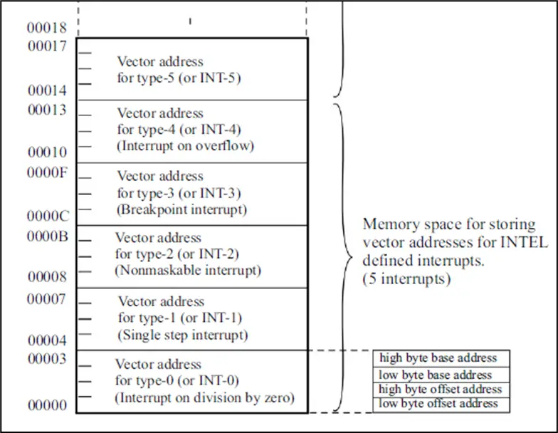
From the above discussion, it is clear that Type 0 occupies the memory locations 00000H to 00003H in the interrupt vector table.
Occupancy of the memory location for Type 1 is 00004H to 00007H and for Type 2 it is from 00008H to 0000BH and so on.
Author of this post
This post is co-authored by Professor Saraswati Saha, who is an assistant professor at RCCIIT, a renowned degree engineering college in India. Professor Saha teaches subjects related to digital electronics & microprocessors.