
Interrupt structure of 8086 | Interrupts in 8086
Last updated on April 12th, 2023 at 05:24 pm
In this post, we will build our concepts on the Interrupt structure of 8086 and discuss various aspects of 8086 interrupts. We will see how many interrupts are there in 8086. And, we will also learn the names of 8086 interrupts. As we must know the types of interrupts in 8086 we have included that as well here. The interrupt structure of 8086 is discussed with the help of the Interrupt Vector Table of 8086.
Interrupt structure of 8086
Here, we will understand the fundamentals of an interrupt in a microprocessor. Also, we will study the Interrupt cycle of 8086 and ISR in 8086.
What is interrupt in microprocessor?
An Interrupt is a condition that halts the microprocessor temporarily so that the microprocessor can work on a different task and then return to its previous task. Interrupt allows peripheral devices to access the microprocessor.
Whenever an interrupt occurs the processor completes the execution of the current instruction and starts the execution of an Interrupt Service Routine (ISR). ISR is a program that tells the processor what to do when the interrupt occurs. After the execution of ISR, the control returns back to the main program where it was interrupted.
Interrupt cycle of 8086 | ISR in 8086
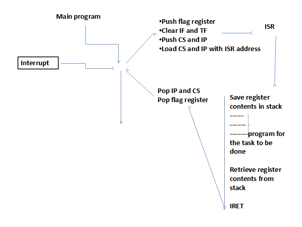
In the 8086 microprocessor, the following tasks are performed if an interrupt has been requested:
- The value of the flag register is pushed into the stack. It means that first the value of SP (Stack Pointer) is decremented by 2 then the value of the flag register is pushed to the memory address of the stack segment.
- The value of starting memory address of CS (Code Segment) is pushed into the stack.
- The value of IP (Instruction Pointer) is pushed into the stack.
- IP is loaded from word location (Interrupt type) * 04.
- CS is loaded from the next word location.
- The interrupt flag (IF) and Trap flag (TF) are reset to 0 to disable the INTR interrupt and single step or trap interrupt respectively.
The following flow diagram shows the processing of an interrupt by the 8086.
Types of interrupts in 8086
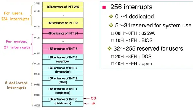
There are 256 interrupt types in the 8086. Among these, a few interrupt types are assigned for specific interrupts such as the divide-by-0 interrupt and the NMI interrupt. A few interrupt types are reserved by Intel for future expansion. The programmer is free to use the remaining interrupt types according to his /her requirement.
The following image shows the classification of interrupts that we have in the 8086 microprocessor.
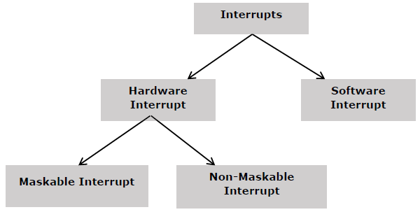
This image shows the classification of interrupts that we have in the 8086 microprocessor.
Hardware Interrupts in 8086
A hardware interrupt is caused by any peripheral device by sending a signal through a specified pin to the microprocessor. The 8086 has two hardware interrupt pins, i.e. NMI and INTR. NMI is a non-maskable interrupt and INTR is a maskable interrupt having lower priority. One more interrupt pin associated is INTA called interrupt acknowledge.
NMI
It is a single non-maskable interrupt pin (NMI) having higher priority than the maskable interrupt request pin (INTR) and it is of type 2 interrupt.
When this interrupt is activated, these actions take place −
- Completes the current instruction that is in progress.
- Pushes the Flag register values onto the stack.
- Pushes the CS (code segment) value and IP (instruction pointer) value of the return address onto the stack.
- IP is loaded from the contents of the word location 00008H.
- CS is loaded from the contents of the next word location 0000AH.
- The interrupt flag and trap flag are reset to 0.
INTR
The INTR is a maskable interrupt because the microprocessor will be interrupted only if interrupts are enabled using set interrupt flag instruction. It should not be enabled using clear interrupt Flag instruction.
The INTR interrupt is activated by an I/O port. If the interrupt is enabled and NMI is disabled, then the microprocessor first completes the current execution and sends ‘0’ on the INTA pin twice. The first ‘0’ means INTA informs the external device to get ready and during the second ‘0’ the microprocessor receives the 8 bit, say X, from the programmable interrupt controller.
These actions are taken by the microprocessor −
- First completes the current instruction.
- Activates INTA output and receives the interrupt type, say X.
- Flag register value, CS value of the return address, and IP value of the return address are pushed onto the stack.
- IP value is loaded from the contents of word location X × 4
- CS is loaded from the contents of the next word location.
- The interrupt flag and trap flag is reset to 0
Software Interrupts | Software interrupts in 8086
Some instructions are inserted at the desired position into the program to create interrupts. These interrupt instructions can be used to test the working of various interrupt handlers. It includes INT. The details of INT are given below.
INT- Interrupt instruction with type number
It is 2-byte instruction. The first byte provides the op-code and the second byte provides the interrupt type number. There are 256 interrupt types under this group.
Its execution includes the following steps −
- The flag register value is pushed onto the stack.
- CS value of the return address and IP value of the return address are pushed onto the stack.
- IP is loaded from the contents of the word location ‘type number’ × 4
- CS is loaded from the contents of the next word location.
- Interrupt Flag and Trap Flag are reset to 0
The starting address for the type 0 interrupt is 00000H, for the type 1 interrupt is 00004H similarly for the type 2 is 00008H, and ……so on. The first five interrupts are dedicated interrupt pointers. i.e. −
- TYPE 0 interrupt represents division-by-zero situation.
- TYPE 1 interrupt represents single-step execution during the debugging of a program.
- TYPE 2 interrupt represents non-maskable NMI interrupt.
- TYPE 3 interrupt represents break-point interrupt.
- TYPE 4 interrupt represents overflow interrupt.
The interrupts from Type 5 to Type 31 are reserved for other advanced microprocessors, and interrupts from Type 32 to Type 255 are available for hardware and software interrupts.
Name the interrupts of 8086
The names of hardware interrupts are: NMI, INTR
The names of software interrupts are: INT n [where n = 0 to 255]
The names of the dedicated interrupts in 8086 are BreakPoint Interrupt, Interrupt on overflow, Divide-by-zero interrupt, Single Step interrupt, and NMI interrupt.
Dedicated interrupts in the 8086
INT 03 – BreakPoint Interrupt Instruction
It is a 1-byte instruction having op-code CCH. These instructions are inserted into the program so that when the processor reaches there, then it stops the normal execution of the program and follows the break-point procedure.
Its execution includes the following steps −
- The flag register value is pushed onto the stack.
- CS value of the return address and the IP value of the return address are pushed onto the stack.
- IP is loaded from the contents of the word location 3×4 = 0000CH
- CS is loaded from the contents of the next word location.
- Interrupt Flag and Trap Flag are reset to 0
INTO – Interrupt on overflow instruction
It is a 1-byte instruction and their mnemonic INTO. The op-code for this instruction is CEH. As the name suggests it is a conditional interrupt instruction, i.e. it is active only when the overflow flag is set to 1 and branches to the interrupt handler whose interrupt type number is 4. If the overflow flag is reset then, the execution continues to the next instruction.
Its execution includes the following steps −
- Flag register values are pushed onto the stack.
- CS value of the return address and IP value of the return address are pushed onto the stack.
- IP is loaded from the contents of word location 4×4 = 00010H
- CS is loaded from the contents of the next word location.
- Interrupt flag and Trap flag are reset to 0
Type 00H or Divide-by-zero interrupt
Whenever the quotient from DIV or IDIV operation is too large to fit in the result register, the 8086 automatically generates a type0 interrupt.
Type 01H or Single Step interrupt
If the TF in the 8086 is set, the 8086 automatically generates a type1 interrupt after each instruction in the main program is executed. After executing the IRET instruction in the ISR, the 8086 again goes to execute the next instruction in the main program.
Type 02H or NMI interrupt
It is a single non-maskable interrupt pin (NMI) having higher priority than the maskable interrupt request pin (INTR) and it is of type 2 interrupt.
When this interrupt is activated, these actions take place −
- Completes the current instruction that is in progress.
- Pushes the Flag register values onto the stack.
- Pushes the CS (code segment) value and IP (instruction pointer) value of the return address onto the stack.
- IP is loaded from the contents of the word location 00008H.
- CS is loaded from the contents of the next word location 0000AH.
- The interrupt flag and trap flag are reset to 0.
Interrupt Vector Table in 8086 | IVT in 8086
The 8086 microprocessor maintains an Interrupt vector table (IVT) which stores the information regarding the location of interrupt service routines (ISR) of various interrupts. In a very simple way, whenever an interrupt occurs, the memory location of ISR is determined using the vector table, and the program control branches to ISR after saving the flags and the program location (the content of the Instruction pointer and code segment register) in the stack.
The IVT can be up to 1kB starting from 00000H to 003FFH of the main memory. For each interrupt, the following is stored:
- Code segment Register content (16-bit value)
- Instruction pointer content (16-bit value)
Therefore the size for each interrupt vector is 4 bytes. 2 bytes (16 bits) for Code Segment (CS) and 2 bytes for Instruction Pointer (IP). These two determine the memory address, i.e. where the interrupt service routine (ISR) for the interrupt is located.
The total 256 interrupts may be represented (each in 4 bytes) in the vector table. These are identified as Type0 to Type255 interrupts. The external logic passes the vector/type number of the interrupt to the 8086 during the interrupt acknowledge bus cycle. The vector/type number is multiplied by 4 to get the memory location vector/type.
As an example, if the vector/type number of the interrupt is 32, its memory address in the vector table will be 32 X 4 = (128)10=00080H
The 8086 interrupt vector table is shown in the figure below:
Interrupt priority in 8086
The priority structure for various interrupts in the 8086 is as follows:
Interrupts and their priority
- Divide-by-zero, INT n and INTO – Highest Priority
- NMI
- INTR
- Single Step – Lowest priority
Author of this post
This post is co-authored by Professor Saraswati Saha, who is an assistant professor at RCCIIT, a renowned degree engineering college in India. Professor Saha teaches subjects related to digital electronics & microprocessors.