
Timing diagram of INX H in 8085 & Timing diagram of INX B
Last updated on March 20th, 2023 at 05:51 pm
In this post, we will discuss the Timing diagram of INX H in 8085. The timing diagram of INX B is also discussed.
In the 8085 Instruction set, INX H stands for “INcrement eXtended register” and H stands for H-L register pair. This instruction will be used to add 1 to the present content of the H-L pair.
And thus the result of the incremented content will remain stored in the H-L pair itself. Though it is an arithmetic instruction flag bits are not at all affected by the execution of this instruction. A register pair is generally used to store a 16-bit memory address.
If flag bits got affected during the increment of a memory address, then it may cause problems in many cases. So as per the design of 8085, flag bits are not getting affected by the execution of this instruction INX H.
INX H
Instruction INX H is a one-byte instruction, and it does not require data from memory or store data in memory. It occupies only 1 Byte in memory and only an opcode fetch cycle is required to execute this instruction.
| Mnemonics Operand | Opcode (in HEX) | Bytes |
| INX H | 23 | 1 |
INX B
Let us consider INX B as a sample instruction falling in this category. As it is a 1-Byte instruction, it will occupy a single-byte location in the memory. Let us consider that the initial content of register pair BC is 4050H. So after the execution of the instruction INX B, the new content of the BC register pair would be 4051H. The result of the execution of this instruction is shown below with the help of a timing diagram.
| Register Pair | Before | After |
| (BC) | 4050H | 4051H |
| Address | (H) Hex Codes | Mnemonic | Comment |
| 2003 | 03 | INX B | BC = BC + 1 |
Here we are considering that the hex code (Machine code) 03H, for the instruction INX B, is stored in memory location 2003H. To fetch this hex cod, the higher order and lower order address are given by the program counter and then the program counter is incremented by one to point to the next instruction.
The opcode fetch of INX needs more time for decoding the opcode and internal operations so T5 and T6-states are required. Whereas for other one-byte general instructions, opcode fetch takes only T1 to T4-states.
Timing Diagram of INX B
Here is the timing diagram of the instruction execution INX B as below:
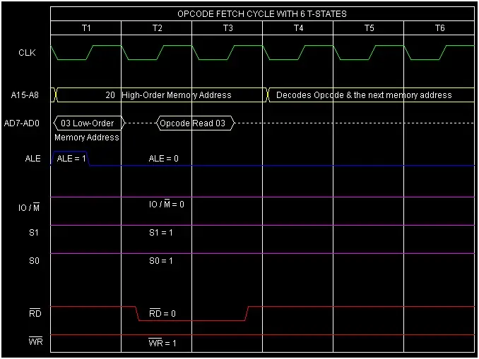
Fig 1: Timing diagram of the instruction INX B.
- During T1, ALE remains high, and the content over AD0-AD7 will be the Low-Order memory byte (Here it is 03H). Similarly, the content over A8-A15 will be the High order memory byte (Here it is 20H) and it remains for T1 to T3-states.
- During T2 and T3 the ALE signal becomes LOW and remains low before starting the next machine cycle. AD0-AD7 is now acting as data bus D0-D7. The RD’ (Active low read control signal) signal goes low during the T2 and T3 states and the processor now read the hex code(03H)from the memory location 2003H.
- As the processor fetches opcode from memory, so IO/M’ signal remains Low during the total execution period to indicate that it is a memory-related operation.
- Two status lines S0 and S1 will be 1,1 to indicate that microprocessor is busy fetching the opcode.
- The opcode fetch of INX needs more time for decoding the opcode and internal operations, so T4, T5, and T6-states are required.
Instruction INX B requires 1-Byte, 1-Machine Cycle (Opcode Fetch), and 6 T-States for execution as shown in the timing diagram.
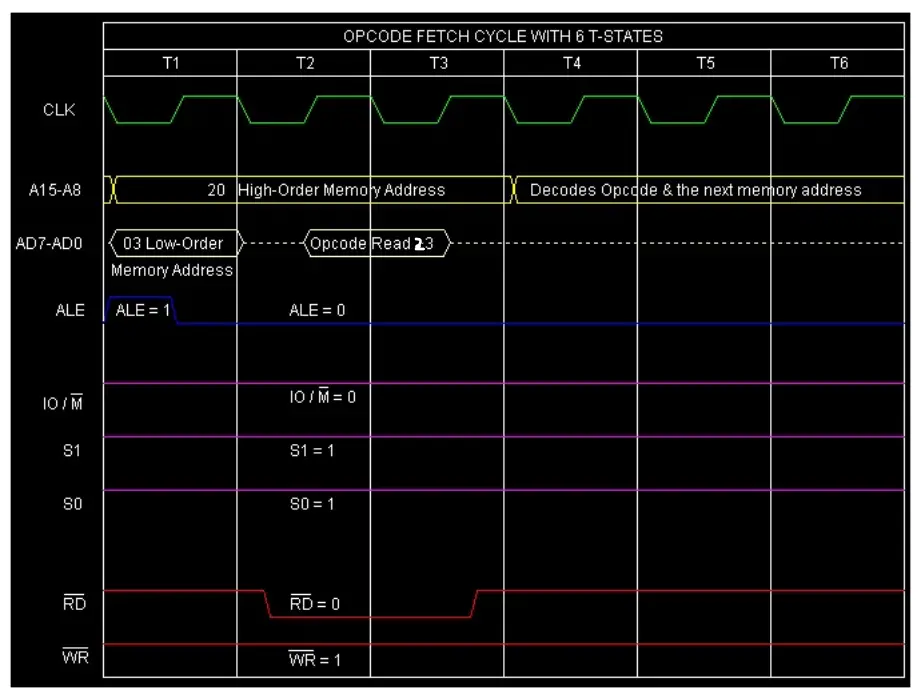
Timing Diagram of INX H
Similarly, INX H also requires 6 T-States to execute it. The only notable difference is in the machine code for the instruction INX H, which will be 23 H.
Here is the Timing Diagram of INX H.
Author of this post
This post is co-authored by Professor Saraswati Saha, who is an assistant professor at RCCIIT, a renowned degree engineering college in India. Professor Saha teaches subjects related to digital electronics & microprocessors.