
Voltages in series circuits and parallel circuits – easy understanding
Last updated on May 6th, 2021 at 10:04 pm
Voltages in series circuits and parallel circuits – Let’s see how total voltage in series circuits and parallel circuits are calculated.
Voltages in series circuits
A series circuit has no junction. Now if there is any group of EMFs that follow in series in such junctionless circuit then the total voltage or emf of the circuit will be the sum of the individual values, that accounts for the direction of their positive and negative sides.
For example, two 1.5 V cells in a TV remote control will be in series, so that the total voltage or emf supplied by them is 3 V. This is also true for any string of potential differences in series.
EMFs in series will add up but their direction is to be considered
EMFs in series will add up. Their direction is to be taken care of as cells in opposite directions oppose each other and cancel out the emf they would supply.
The next diagram has 4 sections with each section showing different combinations of EMFs or cells.
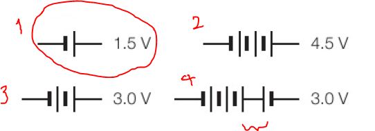
Explanation of the Diagram
- In the diagram above, one 1.5 V EMF is unit is shown in section (1).
- In section 2 of the diagram, three such EMF units (1.5 V each) are connected in series. And as the EMFs are connected in such a way that the positive pole of one unit is connected to the negative pole of the next one, these three EMFs are added up to give 4.5 V EMF.
- Similarly, in section 3 of the diagram, 2 units are connected to give a total of 3 V EMF.
- The last part (section 4) of the above diagram shows 4 EMFs in series. But this combination or interconnection of the EMFs is a bit different. Here, the right-most EMF or cell is connected in the opposite direction. Hence, for this one the total EMF is = (1.5 x 3) -1.5 = 3 V
Total Potential difference or Voltage drop across resistors and Supply Voltage in a series circuit
In the next figure, two resistors are in series, and a 6 V supply is connected to the circuit in series, as shown.
Potential Difference(PD) across each of the resistors is checked with Voltmeter and values are also shown. What would be the total PD across two resistors in figure 2?
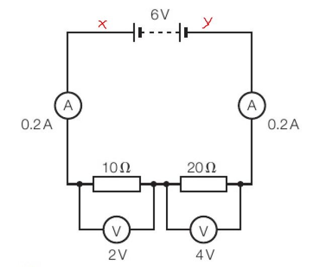
The total Potential Difference(PD) or voltage drop across 2 resistors = sum of two individual PDs = 2 V + 4V = 6 V.
This shows clearly that the total PD in this series circuit equals the supply voltage connected in series to the circuit.
Now let’s discuss the internal physics in the next section.
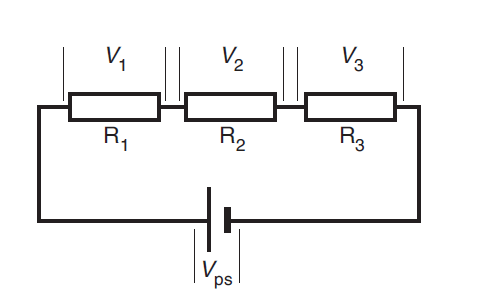
Figure 3 shows three resistors, R1, R2, and R3, connected in series. Vps is the voltage rise in the power supply. V1, V2, and V3 are the voltage drops in the resistors, R1, R2, and R3. As the current flows around the circuit, the potential energy gained by each coulomb of charge in the power supply equals the sum of the potential energies lost by each coulomb of charge in the resistors. Therefore, Vps = V1 + V2 + V3.
If the resistors in the series have equal resistance, the voltage drop across each will be the same. If the resistors in series do not have equal resistance, the resistor with the greater resistance will have a greater voltage drop across it.
Voltage across Series Resistors
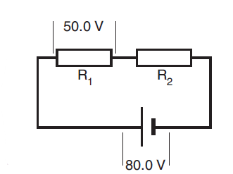
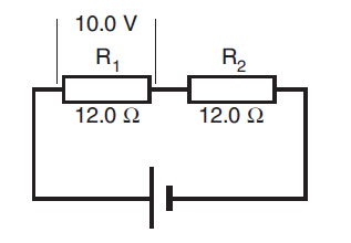
Consider in the circuit shown in figure 4.
(a) Calculate the voltage drop in the resistor R2.
(b) Deduce which resistor has the greater
resistance.
Solution:
(a) The two resistors are in series with the power supply. Therefore:
Vps = V1 + V2
=>80.0 = 50.0 + V2.
So,V2 = 30.0 V.
(b) The greater resistance will have the greater voltage drop across it, therefore R1 has the greater resistance.
Voltage across equal series resistors
For the circuit shown in figure 5, calculate:
(a) the voltage drop across R2
(b) the voltage gain across the power supply.
Solution
(a) As R1 and R2 are equal and connected in series, there will be equal voltage drops across them. Therefore, the voltage drop across R2 is 10.0 V.
(b) Vps = V1 + V2
= 10.0 + 10.0
= 20.0 V
Voltages in Parallel circuits
If the total voltage across any branch of a parallel circuit is known, then the total voltage across any other branch in parallel with it will be identical.
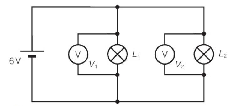
In Figure 6: Both voltmeters in parallel branches here will read 6 V. That is V1=V2=6 V as a cell of 6 V is connected across both the parallel branches.
Let’s discuss more with the following diagram.
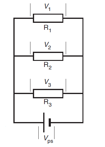
Figure 7 shows three resistors, R1, R2, and R3, connected in parallel. The voltage drops, V1, V2, V3 across the resistors are each equal to the voltage rise, Vps, across the power supply.
To understand this, consider that the potential energy gained by each coulomb of charge in the power supply equals the total potential energy lost by one coulomb of charge in the resistors. As the coulomb of charge passes partly through each resistor, the voltage drop in each resistor must equal the voltage gain in the power supply. That is, Vps= V1 = V2 = V3.
Voltage across parallel resistors
Referring to the circuit shown in figure 8,
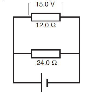
calculate:
(a) the voltage drop across the 24.0 Ω resistor
(b) the voltage gain across the power supply.
Solution
(a) Since the resistors are connected in parallel with the power supply, the voltage drop is the same across each of them. Therefore, the voltage drop across the 24.0 Ω resistor = 15.0 V.
(b) The voltage rise across the power supply equals the voltage drop across each resistor.
Therefore, Vps = 15.0 V.