
Ohm’s law statement with formula & VI Graph | derivation
Last updated on May 7th, 2021 at 04:19 pm
Ohm’s Law states: The potential drop across a resistor is proportional to the current passing through the resistor: V ∝ I. Ohm’s Law applies only to resistors with constant resistance; that is, to resistors whose resistance is the same no matter what current is passing through them. For such resistors: V/I =R (where R is constant). Ohm’s Law can be written: V = IR (where R is constant).
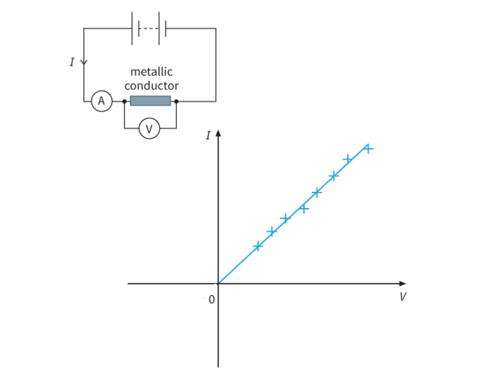
Resistors that obey Ohm’s Law are called ohmic resistors. For an ohmic resistor, the graph of V against I will be a straight line. The slope of the graph will equal the constant resistance. This is illustrated in figure 1. Any component that behaves like this is described as an ohmic component, and we say that it obeys Ohm’s law.
Look at the graph of Figure 1. Such a graph is known as an I–V characteristic. The points are slightly scattered in the graph shown, but they clearly lie on a straight line. A line of best fit has been drawn. You will see that it passes through the origin of the graph. In other words, the current I is directly proportional to the voltage V. The straight-line graph passing through the origin shows that the resistance of the conductor remains constant and it is independent of both the current and the p.d.
Here, in this post, we will discuss more on this and cover the following: Ohm’s Law, Statement, formula derivation, Verification of Ohm’s law with experiment, definition, calculation based on the formula, V-I graph of ohmic and non-ohmic conductors, etc.
- What is Ohm's Law?
- What is the formula for Ohm's law?
- How to derive Ohm's Law formula?
- Draw the VI graph for Ohmic conductors
- Ohmic conductors or ohmic resistor – features
- Draw the VI graph for conductors that behave non-ohmic as temperature rises
- Non-Ohmic conductors or non-ohmic resistors – features
- How can we verify Ohm's Law using an Experiment?
- How to use Ohm's law formula to solve numerical problems
- Conclusion
What is Ohm’s Law?
The potential drop across a resistor is proportional to the current passing through the resistor: V ∝ I. Ohm’s Law applies only to resistors with constant resistance; that is, to resistors whose resistance is the same no matter what current is passing through them. For such resistors: V/I =R (where R is constant). Ohm’s Law can be written: V = IR (where R is constant).
In other words: Ohm’s law states that the current through a metallic element is proportional to the potential difference applied between its ends, provided the temperature remains constant. This statement is also known as Ohm’s Law Statement.
What is the formula for Ohm’s law?
The Ohm’s law formula is like this: V = IR,
Here, V is the Potential difference across 2 ends of a conductor. And the symbol I denotes the current flowing through the conductor while R is the resistance of that conductor.
How to derive Ohm’s Law formula?
If a current I passes through a metallic element when a potential difference V is applied to that element (between its 2 ends), then we can write
I ∝ V
Here comes a proportionality constant (1/R) and the Ohm’s law equation becomes,
I = (1/R) V
=> I = V/R
or, V = IR ………………. (1)
Here, Here R is a constant for the given element and is called its resistance.
So, this law of Ohm can be expressed with the equation or formula, V = IR
Thus, the derivation of Ohm’s law is done.
So we have seen that this law of Ohm can be expressed with the formula or equation, V = IR where V is the potential difference across the metallic element and I is the current flowing through the element. R is the electrical resistance of the element.
Draw the VI graph for Ohmic conductors
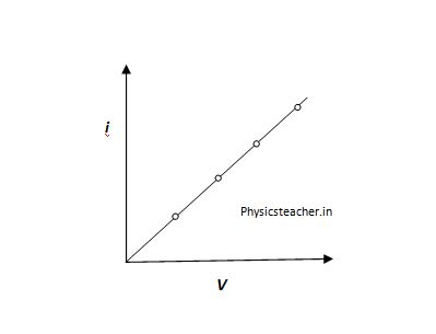
The straight line indicates constant resistance.
Ohmic conductors or ohmic resistor – features
The following are equivalent statements of features about a certain type of resistor that follows Ohm’s law:
- the resistor is an ohmic resistor
- the resistor obeys Ohm’s Law
- the resistance of the resistor is constant
- the graph of V against I for the resistor is a straight line
- voltage is proportional to current for the resistor.
Draw the VI graph for conductors that behave non-ohmic as temperature rises
A device that follows Ohm’s law is said to be ohmic. In reality, no device is perfectly ohmic, though some materials follow approximately ohmic behavior for a wide range of currents.
One reason conductors don’t remain ohmic is that their temperature rises as more current passes through them. The resistance of a normal conductor increases with increasing temperature, which makes it non-ohmic.
An example of this non-ohmic conductor is the metal filament of an incandescent light, which gets quite hot under normal operation.
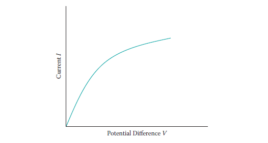
With increasing current, the filament’s temperature increases, raising its resistance.
The changing resistance is revealed by the changing slope of the graph.
Non-Ohmic conductors or non-ohmic resistors – features
The following are equivalent statements about this type of non-ohmic resistor:
- the resistor is non-ohmic
- the resistor does not obey Ohm’s Law
- the resistance of the resistor is not constant
- the graph of V against I for the resistor is not a straight line.
How can we verify Ohm’s Law using an Experiment?
Here we will discuss how we can do an easy experiment to verify Ohm’s law.
What we need for the Experiment or verification test
What we need:
Four or five dry cells,
a thin wire (AB),
a voltmeter,
an ammeter,
a plug key
and some thick connecting wires.
Steps to execute Ohm’s law experiment
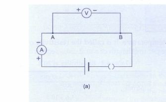
1> We have to start the test with a single cell. We have to connect the circuit as shown in Figure a.
– The ammeter will show us the current I flowing through the circuit, and the voltmeter will measure the potential difference V between the ends A and B of the wire.
– We have to note these values. (1st set of test data) Remember that this set of measured V and I are for a single cell setup.
2> Now we have to connect two cells in series in the circuit, as shown in Figure b.
– We will find that the reading of the voltmeter increases. This means that a larger potential difference has been applied across the wire AB.
– This is obvious as we have in this case applied 2 cells in series.
– We will also find that the reading of the ammeter has increased as well. We have to note down the new values of V and I. (2nd Set of test data)
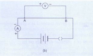
3> We have to repeat the experiment by connecting in series three cells, four cells, and so on. In each case measure the potential difference and the current. (3rd Set, 4th Set….of test data)
4> If we calculate the value of V/I, for each test data set, we will find that it is almost the same.
– So, V/I = R is a constant, which is another way of stating the law of Ohm. Here, R is the resistance of the wire AB.
Ohm’s law graph: If we plot a graph of the current I against the potential difference V, it will be a straight line (Figure c). This shows that the current is proportional to the potential difference.
How to use Ohm’s law formula to solve numerical problems
Q: A 10 V battery is connected to a lamp of resistance 4 Ohm. calculate the current through the lamp.
A: From the law of Ohm, current i = V/R =( 10 / 4 ) A = 2.5 A.
A means Ampere, unit of current.
Now, Try the numerical sets here: Ohm’s Law based Numerical Problems – 3 worksheets
Conclusion
I hope you have liked this post on the law of Ohm. It’s a very interesting and important law of electricity chapter in Physics courses. This law also gives rise to the concept of Resistance. We have published a post on resistance and Numericals on Law of Ohm for high school students.
Another relevant post is Series circuit, equivalent resistance and ohm’s law with solved numerical. Here is one post for parallel circuit as well.