
Kirchhoff’s Voltage law, KVL – statement, formula, example, sign convention
Last updated on June 14th, 2022 at 10:46 am
In this post, we will discuss Kirchhoff’s second law, or Kirchhoff’s Voltage Law (also known as KVL, Kirchoff’s Loop Rule, or Kirchoff’s Loop law) with an example or case study and also write equations for this example. Kirchhoff devised this second law which is based on the energy conservation law. By the way, the first law of Kirchoff is known as KCL.
In an electric circuit, there are sources of emf (often a cell or a battery of cells for dc) and sinks of potential difference or PD (typically, lamps, heating coils, resistors, and thermistors).
A general rule in physics is that energy is conserved.
Electrical components have to obey this too.
So, in any electrical circuit, the energy that is converted into electrical energy (in the sources of emf) must be equal to the energy being transferred from electrical to internal, by the sinks of Potential Difference. This is Kirchhoff’s second law equivalent to the conservation of energy.
This second law applies to all closed circuits – both simple and complex.
KVL – statement
In other words, Kirchhoff’s second law states that In a complete circuit loop, the algebraic sum of the EMFs in the loop is equal to the algebraic sum of the potential differences in the loop.
or
The sum of all variations of potential in a closed-loop equals zero.
KVL In symbols | Kirchoff’s Loop rule formula | KVL formula
For any closed loop in a circuit Σε = ΣIR
KVL example or case study | How to use KVL or Kirchoff’s Loop rule or Kirchoff’s Loop law
Look at the circuit in figure 1, it has parallel and series elements in it. A number of possible loops are drawn and analyzed:
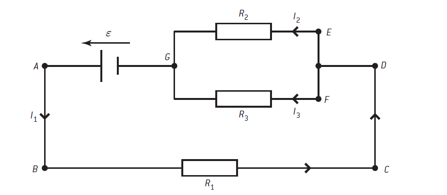
Loop GABCDEG traveling anticlockwise around the loop
This loop begins at the cell and goes around the circuit, through resistor R1 and resistor R2 finally ending at the cell again.
In this loop, there is one source of emf and two sinks of potential difference or PD (ignoring the leads, which we assume have zero resistance).
So ε (the emf of the cell) = I1R1 + I2R2 (i.e., the total pds aross the resistors)
ε = I1R1 + I2R2 ………….. (1)
The direction of loop travel and the current direction are in all cases the same. We give a positive sign to the currents when this is the case. The emf of the cell is driving in the same direction as the loop travel direction; it gets a positive sign as well.
If the loop direction and the current or emf were to be opposed then they would be given a negative sign.
Loop EFGE traveling clockwise around the loop
This loop goes first through resistor R3 and the loop direction is in the same direction as the conventional current.
Next, the loop goes through resistor R1 but this time the current direction and the loop are different so there has to be a negative sign.
There is no source of emf in the loop so the Kirchhoff equation becomes 0 = I3R3 – I2R2
0 = I3R3 – I2R2 ………………… (2)
As we have 3 unknowns (I1, I2, and I3), we will build 3 equations. To build the 3rd equation we will take the help of the KCL. ( we have discussed KCL in a separate post & you can get it here: Know about KCL)
Kirchhoff’s first law can be applied at point G.
The total current into point G is I2 + I3; the total out is I1. The application of the law is I1 = I2 + I3.
I1 = I2 + I3 …………... (3)
There are now three separate equations with three unknowns and these equations can be solved to work out the currents in each part of the circuit assuming that we know the value for the emf of the cell and the values of the resistances in the circuit.
KVL sign convention
The sum of all variations of potential in a closed-loop equals zero – this is the KVL statement for this sign convention. Please note that, In this way of setting the equation, we will put all EMFs and PDs on one side of the equation (say the left-hand side) and put zero on the other side of the equation.
After drawing the currents in different branches of the loops we need to navigate the loops to set up the equations to solve. While navigating the loop in either clockwise or anticlockwise direction, the following sign convention may be adopted to build up the KVL equations.
– if the direction of loop navigation and the direction of a current flow through a resistor are the same, then take this specific PD with a positive (+) sign, and if these are opposite then take the PD with a negative (-) sign in the equation.
– If the direction of loop navigation traverses from the negative pole of a cell to its positive pole, then take this emf with the negative sign. On the other hand, if the direction of loop navigation traverses from the positive pole of a cell to its negative pole, then take this emf with the positive sign.
Remember to put all emf and PDs with appropriate signs on one side of the equation and put zero on the other side of the equation.
Take away
By setting up a series of loops and using KVL it is possible to work out the currents and PDS for complicated resistor networks, more complicated than could be done using the resistor series and parallel rules alone.
Kirchhoff’s second law or KVL is also known as Kirchoff’s Loop rule or Kirchoff’s Loop law.
Kirchoff’s Loop rule or Kirchoff’s Loop law is based on the conservation of energy.