
Generation of time delay in 8085
In this post, we will give you a clear idea of how to generate the time delay using 8085 programs. Through programming time delay can be introduced and this delay will be used in different applications such as traffic signals, digital clocks, process control, and serial data transfer. Generally, a program for the delay is written separately from the main program. And this delay program works as a subroutine when it is called from a main program whenever it is required. When the delay subroutine is executed, the microprocessor does not execute other tasks.
For the delay program, the concept of instruction execution time is very important. Executing some instructions in a loop, a delay is generated. There are some methods of generating delays in microprocessors.
These delay-generating methods are as follows.
- Time delay using one 8-bit register as the counter
- Time delay using 16-bit register pair as the counter
- Time delay using a two Loop technique
- Time delay using NOP instructions
Generation of time delay in 8085 using 8085 Programming – Different techniques
In this section, we will discuss the above-listed methods to generate time delay in 8085 using 8085 programs.
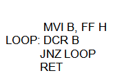
Time delay using one register
In this method, a register is loaded with a number, depending on the time delay required, and then the register is decremented until it reaches zero by setting up a loop with a conditional jump instruction.
The loop causes the delay, depending upon the clock period of the system.
The following program will demonstrate the time delay using one 8-bit register.
Delay Calculations for Time delay using one register
Here the first instruction (MVI B, FF H) will be executed once as it is used to load the register with a number FF H (255 in decimal). It will take 7 T-states.
DCR B instruction takes 4 T-states. This will be executed 255 (FF) times. The JNZ instruction takes 10 T-states when it jumps (It jumps 254 times); otherwise, it will take 7 T-States. And the RET instruction takes 10 T-States.
Therefore Total T- states required for this delay routine is:
=7 + ((4*255) + (10*254)) + 7 + 10
= 3584.
An 8085 microprocessor with a 3 MHz clock frequency will execute the program in (3584 * 1/3 µs) = 1194.66µs. So when we need some small delay, then we can use this technique with some other values in the place of FF.
Note: RET is used to return back to the main program and executed once here.
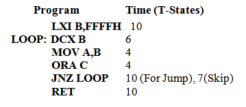
Time delay using a Register Pair
In this method instead of using an 8-bit register (counter), we can do the same task using 16-bit register pair. A register pair is loaded with a number, depending on the time delay required, and then the register is decremented until it reaches zero by setting up a loop with a conditional jump instruction.
Here the instruction DCX does not set the Zero flag and, without the test flags, jump instructions cannot check desired data conditions. Additional two instructions (MOV A, B, and ORA C) must be used to set the Zero flag.
Using this method more time delay can be generated. This method can be used to get more than 0.5 seconds of delay.
The following program will demonstrate the time delay using a register pair.
Delay Calculations for Time delay using a Register Pair
Here the first instruction (LXI B, FFFF H) will be executed once as it is used to load the register pair BC with a number FFFF H (65535 in decimal). It will take 10 T-states.
Thus the total number of T-states taken for the execution of this program will be given by:
10 + (6 + 4 + 4 + 10) * 65535H – 3 + 10 = 17 + 24 * 65535H = 1572857.
So the time delay will be 1572857 * 1/3µs = 0.52428s. Here we are getting nearly 0.5 s delay.
Note: In different programs, we need a 1s delay. In that case, this program can be executed twice. In that case, we can call the Delay subroutine twice or use another outer loop for two-time execution.
Time delay using a Two Loop technique
This loop within a loop or two loop techniques can be explained with a flowchart and the program sequence as shown below.
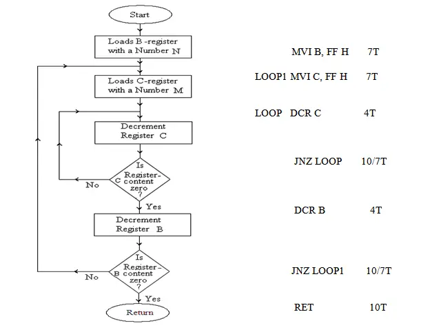
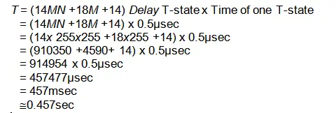
Delay Calculations for Two Loop Technique in 8085
In this subroutine program, M = FF H = 25510 and N = FF H = 25510
Time of one T-state = 0.5μsec (if the system clock is 2 MHz)
Using NOP instructions
One of the main usages of NOP instruction is delay generation.
The NOP instruction takes four clock periods to fetch, decode, and execute the instructions. If the 8085 MPU is working on a 6MHz clock frequency, then the internal clock frequency is 3MHz.
So from that we can easily determine that each clock period is 1/3 of a microsecond. So the NOP will be executed in 1/3 * 4 = 1.333µs.
If we use the entire memory with NOP instructions, then 64K NOP instructions will be executed. Then the overall delay will be 216 * 1.333µs = 87359.488µs.
So this type of NOP instruction can be used to generate a short time delay of a few milliseconds.
Author of this post
This post is co-authored by Professor Saraswati Saha, who is an assistant professor at RCCIIT, a renowned degree engineering college in India. Professor Saha teaches subjects related to digital electronics & microprocessors.