
Potential divider
Last updated on June 23rd, 2023 at 04:57 pm
Sometimes we want to use only part of the e.m.f. of a supply. To do this, we use an arrangement of resistors called a potential divider circuit. In other words, a potential divider is a circuit with an arrangement of resistors that helps us to use only part of the emf of a supply.
What is a potential divider?
A potential divider is a circuit with an arrangement of resistors that helps us to use only part of the emf of a supply.
Potential divider circuit
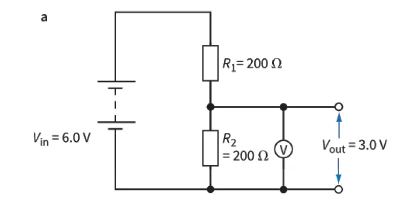
The 2 Figures below show two potential divider circuits, each connected across a battery of e.m.f. 6.0 V and of negligible internal resistance. The high-resistance voltmeter measures the voltage across the resistor of resistance R2. We refer to this voltage as the output voltage, Vout, of the circuit.
Potential divider with fixed resistors
Potential divider with a variable resistor
The first circuit, in figure 1a, consists of two resistors of values R1 and R2. The voltage across the resistor of resistance R2 is half of the 6.0 V of the battery.
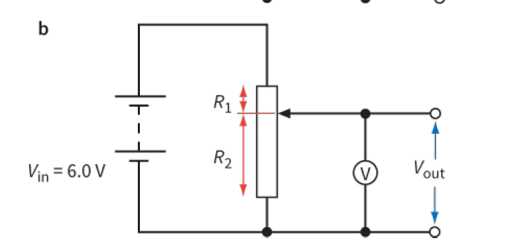
The second potential divider, in Figure 1b, is more useful. It consists of a single variable resistor.
By moving the sliding contact, we can achieve any value of Vout between 0.0 V (slider at the bottom) and 6.0 V (slider at the top).
Potential divider equation | Potential divider formula
The output voltage Vout depends on the relative values of R1 and R2. You can calculate the value of Vout using the potential divider equation: Vout = [R2/(R1 + R2)] x Vin
![Potential divider equation Vout = [R2/(R1 + R2)] x Vin](https://physicsteacher.in/wp-content/uploads/2021/05/image-43.png)
where R2 is the resistance of the component over which the output is taken, R1 is the resistance of the second component in the potential divider and Vin is the p.d. across the two components.
Numerical Question answers based on the potential divider (Practice questions with solution)
Question 1:
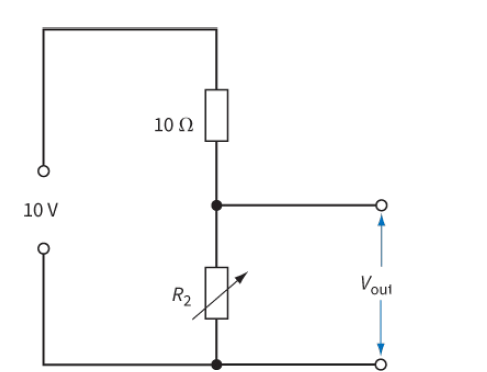
Determine the range of Vout for the circuit in Figure 2 as the variable resistor R2 is adjusted over its full range from 0 Ω to 40 Ω.
(Assume the supply of e.m.f. 10 V has negligible internal resistance.)
Solution:
When the variable resistor R2 = 0, then Vout =0
And, when R2 =40 Ω, then Vout =[ R2/(R2+R1)] x Vin = [40/(40+10)] x 10 V = (4/5)x10 V = 8V. So the range of Vout is 0 V to 8 V.
Question 2:
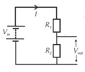
For the circuit in Figure 3, Vin = 9 V and Vout = 6 V.
Suggest one set of possible values for R1 and R2.
Solution:
First, find what fraction Vout is of Vin:
Vout/Vin = 6/9 = 2/3
Vout = (2/3)Vin
Vout = [R2/(R1+R2)]. Vin
So, R2/(R1+R2) = 2/3This multiplies out to give 3R2 = 2R1 + 2R2
=> R2 = 2R1
So you could have, say, R2 = 200 Ω and R1 = 100 Ω.