Generator Effect and Motor Effect – underlying Physics principle
Last updated on December 15th, 2023 at 11:52 am
Generator Effect and Motor Effect – Fleming’s left-hand rule and right-hand rule are the 2 key guidelines for discussing generator effect and motor effect. We will discuss these effects with underlying principles as well as find out the differences between the motor effect and the generator effect.
The Left-hand rule of Fleming tells us about the direction of the force on the current-carrying conductor due to the influence of an external magnetic field at a right angle. This is related to the motor effect.
On the other hand, the right-hand rule of Fleming tells us about the direction of induced current through a conductor that is moving in a magnetic field at a right angle. This rule relates to the Generator effect.
You may read here Fleming’s rules if you want to have a quick revision.
So, let’s find out the underlying principles of these two effects, their differences, and the Physics behind these effects. This post will benefit the students of different boards like IGCSE, GCSE, CBSE, ICSE, etc.
Motor Effect and Generator Effect
If we compare the physics behind the motor and generator operation, then we will see that the underlying principle for both is the same.
This principle can be stated like this: moving electrons experience a force that is mutually perpendicular to both their velocity and the magnetic field they are traveling through.
Motor Effect – Motor Principle | Define motor effect or motor principle
For a motor, current flow in a conductor kept in an external magnetic field causes a deflecting force on the electrons in the conductor, which in turn causes the deflection of the conductor itself. Motion as a result of current in an external magnetic field is called the motor effect. Here electrical energy is converted to mechanical energy.
The motor effect is an interaction of two magnetic fields – Explain why.
A current-carrying conductor produces a magnetic field. When the current-carrying conductor passes through an external magnetic field, the magnetic field of the conductor interacts with the external magnetic field and the conductor experiences a force. This effect was discovered in 1821 by Michael Faraday (1791–1867) and is known as the motor effect.
Explain how the Motor effect follows Fleming’s Left-Hand Rule

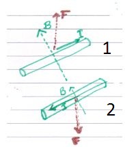
When the charge moves along the wire (fig A above, configuration 1), there is a perpendicular upward force on the charge. Since there is no conducting path the force on the charge tugs the wire upward.
In the same figure see the bottom one, (fig A, configuration 2), where the direction of the current flow is reversed. This time the perpendicular force tugs the wire downward.
All the directions here follow the left-hand rule of Fleming.
How does the deflection of the current-carrying conductor happen in an external magnetic field? | Explain the Motor effect
Let’s discuss in detail the Effect of Magnetic force on Current-carrying wires or the Motor effect. In other words, let’s explain the deflection of the Motor effect.

A current-carrying conductor produces a magnetic field. When this current-carrying conductor passes through an external magnetic field, the magnetic field of the conductor interacts with the external magnetic field and the conductor experiences a force.
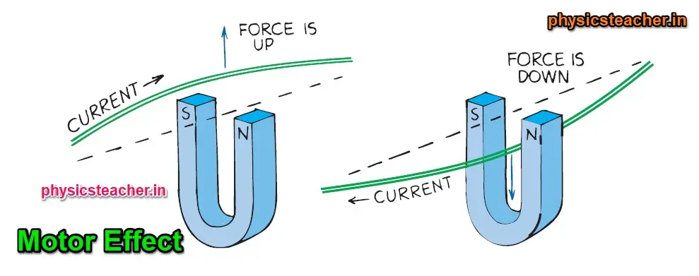
[In Figures B and C above, the initial position of the current-carrying conductor is shown with the dotted line. This conductor is kept within an external magnetic field caused by the U-shaped magnet as shown in figures B and C.]
Logically we can say that if a single charged particle moving through a magnetic field experiences a deflecting force, then a current of charged particles moving through a magnetic field also experiences a deflecting force.
If the particles are part of a wire when they respond to the deflecting force, the wire also gets pushed and deflected (Figure B).
If we reverse the direction of the current, the deflecting force acts in the opposite direction,(Figure C) perpendicular to both field lines and current.
It is a sideways force. This deflecting force is strongest when the current is perpendicular to the magnetic field lines.
Factors affecting the magnitude of the deflecting force on a straight conductor in a magnetic field | Factors affecting Motor effect
The Factors affecting the Motor effect are the factors that affect the deflection of a straight current-carrying conductor in an external magnetic field. As this deflection is caused by a deflection force, we need to find out how this deflection force gets affected.
The magnitude of the deflection force on a straight current-carrying conductor in an external magnetic field depends on the following factors:
• the strength of the external magnetic field. The force is proportional to the magnetic field strength, B
• the magnitude of the current in the conductor. The force is proportional to current, I
• the length of the conductor in the field. The force is proportional to the length, l
• the angle between the conductor and the external magnetic field.
Equation of the deflection force produced due to the motor effect
Here, we will derive the equation of the deflection force on a current-carrying conductor due to the motor effect. This force is also known as the force on a moving current.
The reason for the movement or deflection is due to the interaction of the two magnetic fields – that of the external magnet and the magnetic field produced by the current-carrying wire. This is known as the motor effect and this effect is put to practical use in electric motors.
The deflecting force on the straight current-carrying conductor is at a maximum when the conductor is at right angles to the field produced by the external magnet and it is zero when the conductor is parallel to the field.

The magnitude of the magnetic force F is found to be directly proportional to:
1. the strength of the magnetic field B measured in teslas (T)
2. the current flowing in the wire I measured in amperes (A)
3. the length of the conductor in the magnetic field l that is measured in meters (m).
So that
F = IlB
This force is greatest when the magnetic field is perpendicular to the conductor.
Sometimes the wire in the magnetic field is at an angle θ to the magnetic field.
In this case, the deflecting force can be expressed mathematically as F = IlB sin θ.
This is the equation of the deflection force produced due to the motor effect.
Here, B is flux density (the strength of a magnetic field), I is current measured, and l is the length of the conductor in the magnetic field
Therefore, as θ decreases, so too does the force. When θ = 0° the current in the conductor is moving parallel to the magnetic field and no force on the conductor occurs.
The force experienced can be increased if the number of turns of wire carrying the current is increased.
In this case, the force is given by F = IlBn where n is the number of turns of wire and θ = 90°. When there are several turns of wire suspended between a magnetic field, the device is commonly called a wire toroid.
Generator Effect – Generator Principle | Define the Generator effect
In the case of generators, the law of induction works. Here the current is produced because of the motion of a conductor in the magnetic field. This is called the generator effect. Here mechanical energy is transformed into electrical energy.
Explain how the Generator effect follows Fleming’s Right-Hand Rule

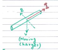
In the figure above, a wire with no initial current is moved downward along the line labeled with V (obviously along with the charges entrapped in the conductor) in a magnetic field (shown by the magnetic field line B).
As a result, the charge in the wire experiences a deflecting force perpendicular to its motion. If you apply Fleming’s right-hand rule you will get the direction of this force (It would be along line I as shown in the figure above)
There is a conducting path in this direction, so the charge moves along the wire itself, constituting a current through the wire itself.
Now if the movement of the wire (with no current) is made in the opposite direction, i.e. upward here, then the direction of the deflecting force on the charges will also reverse.
This results in a current in the opposite direction through the wire.
All the directions here follow the right-hand rule of Fleming.
Motor effect vs Generator effect | Generator effect vs Motor effect | differences
Here we will list the differences between the motor effect and the generator effect in a tabular format.
| Motor Effect | Generator effect |
|---|---|
| 1) Explains the electric Motor operation | 1) Explains the Generator functionality |
| 2) Fleming’s left-hand rule applies to the motor effect | 2) Fleming’s right-hand rule applies to the generator effect. |
| 3) Motion as a result of current in an external magnetic field is called the motor effect. | 3) Here the current is produced because of the motion of a conductor in the magnetic field. This is called the generator effect. |
| 4) Here electrical energy is converted to mechanical energy. | 4) Here mechanical energy is transformed into electrical energy. |
Know about the different uses of Generators and Motors
Reference:
Book: Conceptual Physics by Paul G. Hewitt
Suggested Post: Electric Charge
