
DeMorgan’s theorems of Boolean algebra
Two of the most important theorems of Boolean algebra were contributed by a great mathematician named DeMorgan. DeMorgan’s theorems are extremely useful in simplifying expressions in which a product or sum of variables is inverted.
The two theorems are represented as shown in figure 1 below:

Statements of DeMorgan’s theorems
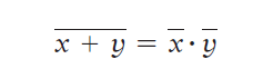
Theorem (1) of DeMorgan says that when the OR sum of two variables is inverted, this is the same as inverting each variable individually and then ANDing these inverted variables.
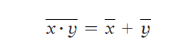
Theorem (2) DeMorgan says that when the AND product of two variables is inverted, this is the same as inverting each variable individually and then ORing them. Each of DeMorgan’s theorems can readily be proven by checking for all possible combinations of x and y.
Implication of DeMorgan’s theorems
DeMorgan’s theorem (1) – Implication:
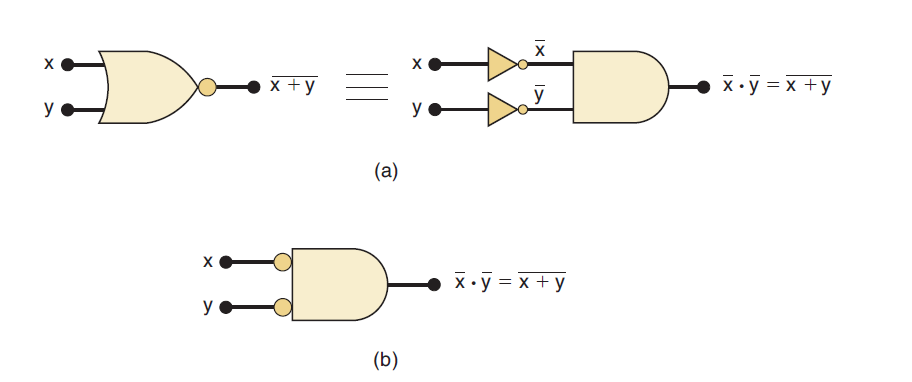
The left-hand side of the equation can be viewed as the output of a NOR gate whose inputs are x and y. The right-hand side of the equation, on the other hand, is the result of first inverting both x and y and then putting them through an AND gate.
These two representations are equivalent and are illustrated in Figure 2(a).
What this means is that an AND gate with INVERTERs on each of its inputs is equivalent to a NOR gate. In fact, both representations are used to represent the NOR function.
When the AND gate with inverted inputs is used to represent the NOR function, it is usually drawn as shown in Figure 2(b), where the small circles on the inputs represent the inversion operation.
DeMorgan’s theorem (2) – Implication:
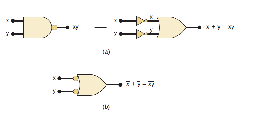
The left side of the equation can be implemented by a NAND gate with inputs x and y. The right side can be implemented by first inverting inputs x and y and then putting them through an OR gate.
These two equivalent representations are shown in Figure 3(a). The OR gate with INVERTERs on each of its inputs is equivalent to the NAND gate. In fact, both representations are used to represent the NAND function.
When the OR gate with inverted inputs is used to represent the NAND function, it is usually drawn as shown in Figure 3(b), where the circles again represent inversion.