
Capacitors & Capacitance
Last updated on May 16th, 2022 at 07:57 pm
Capacitors are components of electrical circuits that temporarily store electric charge. Capacitors are simple passive devices. The capacitor is a component that has the ability or “capacity” to store energy in the form of an electrical charge producing a potential difference across its plates.
Capacitors consist of two or more parallel conductive metal or foil plates that are not connected or touching each other but are electrically separated either by air or by some form of insulating material such as paper, mica, ceramic, or plastic and which is commonly called the capacitors Dielectric.
The addition of a capacitor into a circuit has two possible effects: either introducing a time delay into the circuit; or storing electrical energy for a short period of time.
Use of capacitors: Capacitors are used extensively in electrical and electronic timing circuits, in power circuits, for smoothing electrical signals, and as part of the signal-receiving circuits found in radios.
A capacitor’s ability to become charged by a voltage and then hold that charge indefinitely allows capacitors to be used in electrical and electronic circuits in a variety of ways, from smoothing out fluctuations in voltage power supply levels to timing and filter circuits when used in conjunction with a resistor.
- What is there in a capacitor?
- What are the circuit symbols used for capacitors?
- How does a capacitor work?
- Time required for charging a capacitor
- What is Capacitance? – definition
- Equation of Capacitance | Formula
- Measuring the capacitance of a capacitor
- Units of Capacitance
- Capacitor Types
- Connecting Capacitors Together
- Capacitors in Series
- Capacitors in Parallel
What is there in a capacitor?
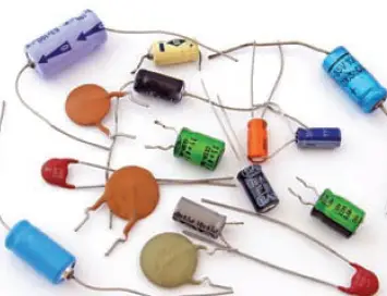
Modern capacitors consist of two parallel conducting plates (usually made of metal foils, films, or coatings) separated by a thin insulating layer known as a dielectric (generally made from thin plastic films, electrolytes, ceramics, or metal oxides). Most capacitors are then encased in a metal or plastic housing. Figure 1 shows a selection of different capacitors.
What are the circuit symbols used for capacitors?
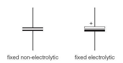
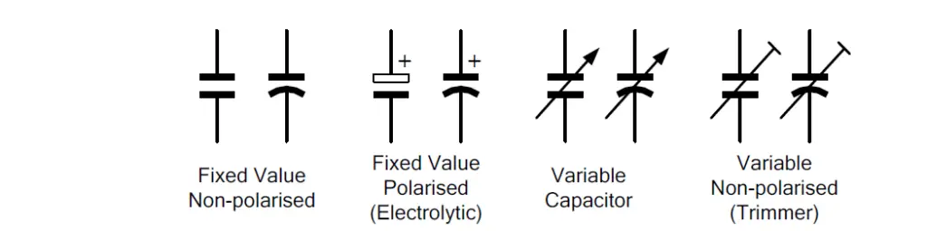
There are several different circuit symbols for capacitors depending on their type, although they are all based on the same simple pattern shown in Figure 2. A bigger set of capacitor symbols are given in figure 2a.
More Symbols are given below:
How does a capacitor work?
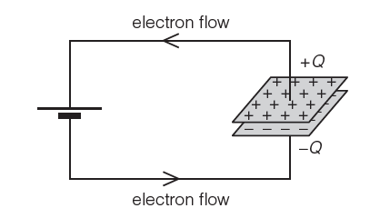
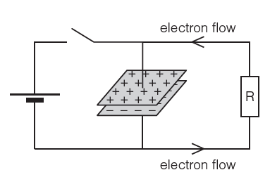
A potential difference from a battery or a power supply connected across the metal plates causes electrons to flow off one plate, back through the battery, and onto the second plate (Figure 3).
One plate becomes positively charged (where electrons are removed), while the plate with the excess of electrons becomes negatively charged.
If the capacitor is then disconnected from the source of potential difference, the charge will stay on the plates until a conducting pathway allows the excess electrons to flow off the negatively charged plate and back onto the positive plate, until the two plates have equal charge again (Figure 4).
The conducting pathway could be a different part of the circuit (controlled by a switch) or the charge could gradually leak away to the surroundings.
Time required for charging a capacitor
When the plates of a capacitor are connected across a DC supply voltage, it takes some time for the charge (in the form of electrons) on the plates to reach their full intensity.
When a sufficient amount of charge, Q (measured in units of coulombs) has been transferred from the source voltage to the capacitor’s plates, the voltage across the plates, Vc will be equal to the source voltage, Vs and the flow of electrons will cease.
The voltage developed across the capacitor’s plates is not instantaneous but builds up slowly at a rate that depends on the capacitance value of the plates, the greater the capacitance, the slower the rate of change of voltage in the plates.
What is Capacitance? – definition
The ability of any object to store charge is called capacitance.
Capacitance is given the symbol C, and the SI unit is the farad (F). The capacitance of a capacitor depends on the area of the metal plates, the distance between the plates, and the electrical properties of the material separating the plates.
Equation of Capacitance | Formula
The amount of charge, Q, that can be stored on a capacitor depends on the size of the capacitance, C, and the potential difference, V, across the capacitor causing the separation of the charge.
The relationship among Q, C, and V is presented by this equation:
Q = VC
The capacitance of a capacitor can then be defined by the following equation:
C= Q/V
For a parallel plate capacitor, the ratio of Q ÷ V is a constant called the capacitance, C.
So one farad is equal to one coulomb per volt.
Then one coulomb of charge exists when a capacitance of one farad is subjected to one volt of potential difference.
Actually, 1 F is quite a large capacitance, and useful ‘real-life’ capacitors have capacitances measured in microfarads (μF), nanofarads (nF), or picofarads (pF).
Measuring the capacitance of a capacitor
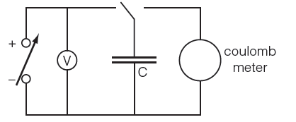
A fully discharged capacitor is connected to a variable d.c. power supply and is then gradually charged to different potential differences. A digital coulombmeter is then used to measure the charge stored on the capacitor at each potential difference
(Figure 5).
The data from this experiment (potential difference and charge stored) can be recorded in a table and you can plot a graph of Q against V from that dataset.
Units of Capacitance
The SI unit of capacitance is the Farad (abbreviated to F) named after the British physicist Michael Faraday. A capacitor has the capacitance of One Farad when a charge of One Coulomb is stored on the plates by a voltage of one volt. Capacitance, C is always positive and has no negative units.
However, the Farad F is a very large unit of measurement to use on its own, so sub-multiples of the Farad are generally used such as micro-farads, nano-farads, and pico-farads, for example.
Microfarad (μF) 1μF = 10-6 F
Nanofarad (nF) 1nF = 10-9 F
Picofarad (pF) 1pF = 10-12 F
Capacitor Types
The names that are used to describe the different types of capacitors are the names of the dielectric materials used in its construction because the performance of a capacitor is usually dependant upon the type of material that is used for its dielectric.
The various types of capacitors include disc and tubular ceramics made from aluminium oxide or titanium oxide, silvered mica, metalized film made using strips of waxed or oiled paper and aluminium foil, or with plastic dielectrics such as polyethylene, mylar, polypropylene, polycarbonate, and polyester, and finally large electrolytic capacitors in the form of Aluminum Electrolytic Capacitors and Tantalum Electrolytic Capacitors either polarised or non-polarised.
Variable capacitors change value due to the variation in the overlapping area of the plates, or by varying the spacing between parallel plates.
Air dielectric is used for the larger capacitance values.
Trimmers and smaller variable types use very thin mica or plastic sheets as the dielectric between the plates.
Connecting Capacitors Together
Like resistors, capacitors can be connected in series, parallel, and series-parallel combinations.
Placing capacitors in series effectively increases the thickness of the dielectric, decreases the total capacitance.
Connecting capacitors together in parallel effectively increases the area of the plates making the total capacitance equal to the sum of the individual capacitances like the total resistance of series resistors. Capacitors in parallel all charge to the same voltage.
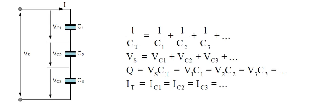
Capacitors in Series
Capacitors are said to be connected together “in series” when they are effectively “daisy-chained” together in a single line.
The charging current (Ic) flowing through the capacitors is the same for all capacitors as it only has one path to follow. Then, Capacitors in Series all have the same current so each capacitor stores the same amount of charge regardless of its capacitance.
Capacitors connected together in series all have the same amount of charge.
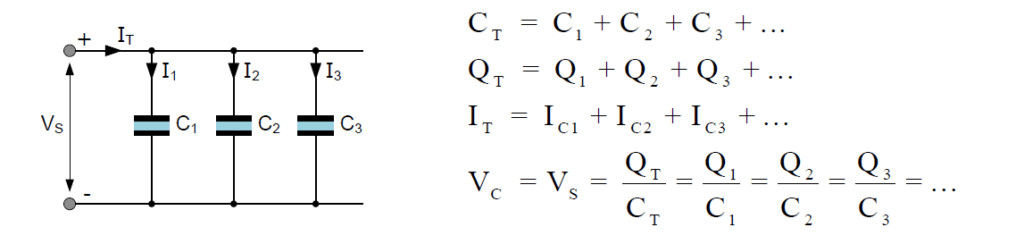
Capacitors in Parallel
Capacitors are said to be connected together “in parallel” when both of their terminals are respectively connected to each terminal of the other capacitor or capacitors. The voltage, Vs connected across all the capacitors that are connected in parallel is the same. Then, Capacitors in Parallel have a common voltage supply across them.
Related study: Inductor & Inductance