
Seebeck effect
In this post, we will discuss the Seebeck effect or thermoelectric effect and other related points like thermocouple, thermoelectric emf, thermoelectric series, variation in thermoelectric emf with temperature, Neutral and Inversion temperature, etc.
Seebeck effect or thermoelectric effect
In 1821, German Physicist Thomas Johann Seebeck discovered that in a circuit consisting of two dissimilar metals like iron and copper, an emf is developed when the junctions are maintained at different temperatures. Two dissimilar metals connected to form two junctions is called a thermocouple. The emf developed in the circuit is thermoelectric emf. The current through the circuit is called thermoelectric current. This effect is called the thermoelectric effect or the Seebeck effect.
If the hot and cold junctions are interchanged, the direction of the current also reverses. Hence Seebeck effect is reversible. In a Cu-Fe thermocouple (Fig 1a), the direction of the current is from copper to iron at the hot junction (fig 1b)
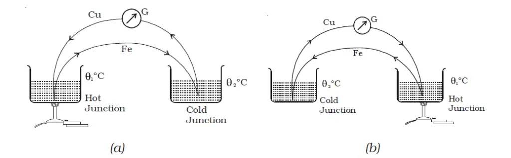
The magnitude and sign of thermo-emf depend on the materials of the two conductors and the temperatures of the hot and cold junctions.
thermoelectric emf definition
In a circuit consisting of two dissimilar metals like iron and copper, an emf is developed when the junctions are maintained at different temperatures. The emf developed in the circuit is thermoelectric emf. The current through the circuit is called thermoelectric current.
thermoelectric series
Seebeck after studying the thermoelectric properties of different pairs of metals arranged them into a series called the thermoelectric series. The direction of the current at the hot junction is from the metal occurring earlier in the series to the one occurring later in the series.
The magnitude of thermoelectric emf is larger for metals appearing farther apart in the series. The thermo-electric series of metals is :
Bi, Ni, Pd, Pt, Cu, Mn, Hg, Pb, Sn, Au, Ag, Zn, Cd, Fe, Sb.
variation in thermoelectric emf with temperature | thermoelectric emf and its temperature dependence
The thermoelectric emf of any thermocouple has the temperature dependence given by the relation, V = α θ + ½ β θ2, where θ is the temperature difference between the junctions and α and β are constants depending on the nature of the materials.
The graph showing the variation of the thermoelectric emf with the temperature of the hot junction, taking the temperature of the cold junction (θC) as the origin is shown in Figure 2. For a small difference in temperature between the junctions, the graph is a straight line. For the large difference in temperature, the graph is a parabola.
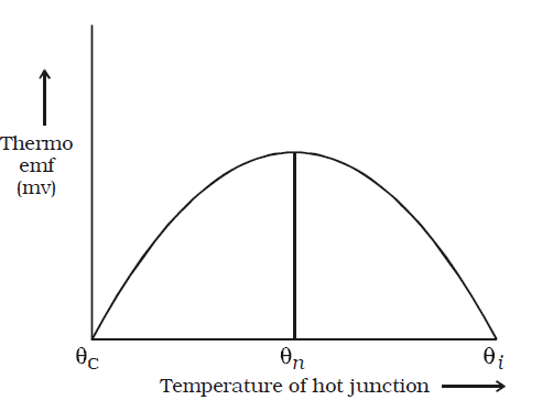
Keeping the temperature of the cold junction constant, the temperature of the hot junction is gradually increased. The thermoelectric emf rises to a maximum at a temperature (θn) called neutral temperature and then gradually decreases and eventually becomes zero at a particular temperature (θi) called temperature of inversion.
Beyond the temperature of inversion, the thermoelectric emf changes sign and then increases.
For a given thermocouple, the neutral temperature is a constant, but the temperature of inversion depends upon the temperature of cold junction.
Neutral and Inversion temperature relationship – a formula
The Neutral and Inversion temperature relationship can be expressed by the formula ( θC + θi ) /2 = θn