
P–V diagram & calculation of work done
In this post, we will discuss how the P-V diagram can help us to calculate the work done by a system or on a system. We will derive the equation of work done in terms of pressure and volume. We will solve a few numerical problems as well based on P-V diagrams.
- Setup to get a P-V diagram
- Drawing a P-V diagram
- Equation of Work done in terms of Pressure and Volume (when pressure is constant in a p-v diagram) – derivation
- Calculating the work done from P-V diagram when pressure P changes
- Work done depends on the path between the initial and final states
- Solving numerical using P-V diagram
Setup to get a P-V diagram
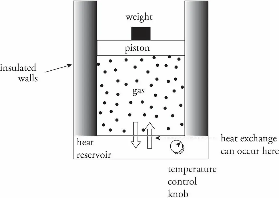
- Consider the following example. An insulated container filled with an ideal gas rests on a heat reservoir (something that can act as a heat source or a heat sink).
- The container is fitted with a snug, but frictionless, weighted piston that can be raised or lowered.
- The confined gas is the system, and the piston and heat reservoir are the surroundings.
Drawing a P-V diagram
The state of the gas is given once its pressure, volume, and temperature are known, and the equation that connects these state variables is the ideal gas law, PV = nRT.
We’ll imagine performing different experiments with the gas, such as heating it or allowing it to cool, increasing or decreasing the weight on the piston, and so on.
And then we will study the energy transfers (work and heat) and the changes in the state variables.
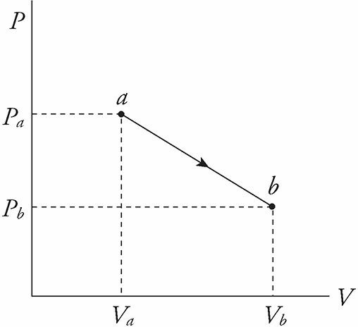
If each process is carried out such that at each moment, the system and its surroundings are in thermal equilibrium, we can plot the pressure (P) versus the volume (V) on a diagram. This is the P-V diagram.
By following the path of this P–V diagram, we can study how the system is affected as it moves from one state to another.
Equation of Work done in terms of Pressure and Volume (when pressure is constant in a p-v diagram) – derivation
Work is done on or by the system when the piston is moved and the volume of the gas changes. For example, imagine that the gas pushes the piston upward, causing an increase in volume.
The work done by the gas during its expansion is W = FΔs,
but since F = PA, we have W = PAΔs, and because AΔs = ΔV, we have W = PΔV
W = FΔs
work done equation is derived here assuming constant pressure during the process
=>W = PA Δs
=> W = PΔV
This equation is also true if the piston is pushed down and the volume of the gas decreases. In this case, ΔV is negative, so W is negative.
In general, then, W is positive when the system does work against its surroundings, and W is negative when the surroundings do work on the system.
The equation W = PΔV assumes that the pressure P does not change during the process.
Calculating the work done from P-V diagram when pressure P changes
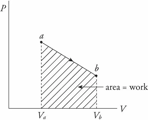
If pressure P does change, then the work is equal to the area under the curve in the P−V diagram; moving left to right gives a positive area (and positive work) while moving right to left gives a negative area (and negative work).
Work done depends on the path between the initial and final states
The value of W depends not only on the initial and final states of the system but also on the path between the two. In general, different paths give different values for W. This will be clear as you observe the p-v diagram in figure 4 below and solve the concerned numerical.
Solving numerical using P-V diagram
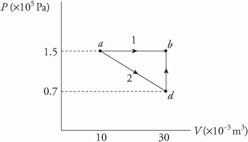
1 ) Follow figure 3. What’s the value of W for the process ab following path 1 (a to b) and for the same process following path 2 (a to d, d to b), shown in the P−V following diagram?
Solution:
Path 1.
Since, in path 1, P remains constant, the work done is just PΔV.
W = PΔV = (1.5 × 10⁵ Pa)[(30 × 10−3 m3) − (10 × 10−3 m3)] = 3,000 J
Path 2.
If the gas is brought from state a to state b, along path 2, then work is done only along the part from a to d. From d to b, the volume of the gas does not change, hence, ΔV =0. So no work can be performed. The area under the graph from a to d is
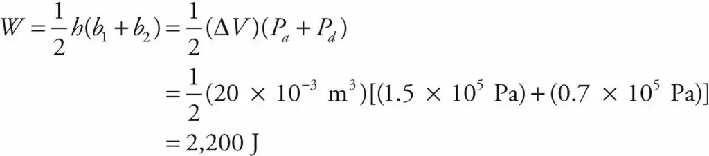
As this example shows, the value of W depends not only on the initial and final states of the system, but also on the path between the two. In general, different paths give different values for W.
Questions 2-3
For the previous P−V diagram,
2) Find the work done by the system for the path abda.
3) Find the heat absorbed by the system along this same path.
Solution:
Solution for 2 )
From the previous problem, we learned that, for the process ab, W = 3,000 J, and for process bd, W = 0. Since W = 2,200 J for the
process ad, then W for da would be −2,200 J (ΔV is negative.)
Therefore, the total W = 3,000 J − 2,200 J = 800 J.
Solution for 3 )
Since U depends on the state of the system, for any closed path on a P−V diagram, ΔU = 0. Since ΔU = Q − W,
we have 0 = Q − 800 J, therefore Q = 800 J.