
How does alternating current differ from direct current?
Last updated on September 11th, 2021 at 08:23 am
In this post, we will find out the answer to a very common question: “How does alternating current differ from direct current?”
Direct current implies that the current flows in a single direction from the positive terminal of a battery or power supply to the negative terminal. This is the normal result when a battery is used. Alternating current, on the other hand, continually reverses its direction – it flows first in one direction, then in the other, and then back again.
The battery in a torch makes the current go around the circuit in one direction only. The current in the circuit is called a direct current(d.c,) because it is in one direction only.
When you switch a light on at home, you use alternating current (a.c.) because mains electricity is an a.c. supply. An alternating current repeatedly reverses its direction. It flows one way then the opposite way in successive cycles. Its frequency is the number of cycles it passes through each second.
The alternating current used in North America goes through 60 back-and-forth cycles each second, so its frequency is 60 cycles per second, or 60 hertz (Hz). In the UK and India, this frequency is 50 Hz.
Mains circuits
Every mains circuit has a live wire and a neutral wire. The current through a mains appliance alternates. That is because the mains supply provides an alternating potential difference between the two wires.
In other words, the polarity of the potential difference repeatedly reverses its direction. In comparison, potential differences in direct current circuits do not change direction.
The neutral wire is earthed at the local electricity substation. The potential difference between the live wire and the earth is usually called the potential or voltage of the live wire.
The live wire is dangerous because its potential repeatedly changes from + to – and back every cycle. In UK homes, it reaches about 325V in each direction.
Simple Galvanometer & its reaction to AC
A galvanometer is an ammeter designed so that the needle will deflect in either direction, depending on the direction of the current. If we placed a galvanometer in an alternating-current circuit, the needle would fly back and forth rapidly—assuming that the meter could actually keep up with the changes. Because simple galvanometers cannot respond to such swift changes, the usual result is that the needle vibrates but remains centered on zero. The average value of an ordinary alternating current is zero.
Oscilloscope and AC | sinusoidal curve
An oscilloscope is an electronic instrument that plots electric voltage as it varies with time.
We can use an oscilloscope to measure a current by displaying the voltage difference across a resistance in the circuit (ΔV = IR). For an alternating current, the resulting graph would look like figure 1.
In this figure, AC frequency is taken as 60 Hz. That means, 60 cycles take 1 second. Hence, the tile period = T = time for one complete cycle = 1/60 seconds. This is shown in figure 1 below.
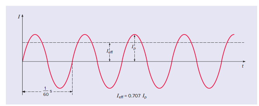
On this graph, positive values of current represent one direction of flow, and negative values of current represent the opposite direction. This curve is called a sinusoidal curve because it is described by a trigonometric function, the sine.
Investigating an alternating potential difference with oscilloscope
An oscilloscope is used to show how an alternating potential difference changes with time.
1) Connect a signal generator to an oscilloscope (Figure 2).
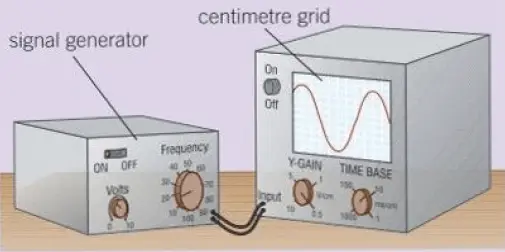
– The waves on the oscilloscope screen are caused by the potential difference increasing and decreasing continuously.
Adjusting the ‘Y-gain’ control changes how tall the waves are. And, adjusting the ‘time base’ control changes how many waves fit across the screen.
– The peak potential difference (peak voltage) is the difference in volts between the highest level and the middle level of the waves. Increasing the potential difference of the a.c. supply makes the waves on the screen taller.
– Increasing the frequency of the a.c. supply increases the number of cycles you see on the screen. So the waves on the screen get squashed together.
Battery and oscilloscope | DC voltage & oscilloscope
If a battery (DC voltage) is connected to the oscilloscope, you should see a flat line at a constant potential difference.
Alternating Voltage equation
Alternating current is produced in power stations by large generators.
A generator consists of a coil rotating in a magnetic field. An e.m.f. is induced in the coil according to Faraday’s and Lenz’s laws of electromagnetic induction.
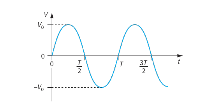
This e.m.f. V varies sinusoidally, and so we can write an equation to represent it: V = V0 sin ωt, where V0 is the peak value of the voltage. This equation of alternating voltage has the same form as the equation for alternating current.
We can also represent this graphically, as shown in Figure below:
Key points
- Direct current (d.c.) flows in one direction only. Alternating current (a.c.) repeatedly reverses its direction of flow.
- A mains circuit has a live wire, which is alternately positive and negative every cycle, and a neutral wire at zero volts.
- The peak potential difference of an a.c. supply is the maximum voltage measured from zero volts.
- To measure the frequency of an a.c. supply, measure the time period of the waves, then use the equation frequency= 1/ time taken for 1 cycle