
Process Control Loop – components [Process control & Instrumentation primer]
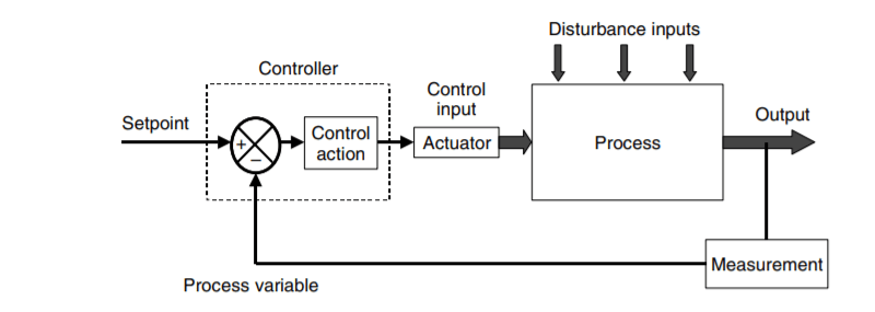
Most basic process control systems consist of a control loop as shown in Figure 1, having four main components:
- A measurement of the state or condition of a process
- A controller calculating an action based on this measured value against a preset or desired value (setpoint)
- An output signal resulting from the controller calculation, which is used to
manipulate the process action through some form of actuator - The process itself reacting to this signal, and changing its state or condition.
Two of the most important signals used in process control are called
- Process variable or PV
- Manipulated variable or MV.
Process Variable or PV
In industrial process control, the Process variable(PV) is measured by an instrument in the field and acts as an input to an automatic controller which takes action based on the value of it.
Alternatively, the PV can be an input to a data display so that the operator can use the reading to adjust the process through manual control and supervision.
Manipulated variable or MV
The variable to be manipulated, in order to have control over the PV, is called the MV.
For instance, if we control a particular flow, we manipulate a valve to control the flow. Here, the valve position is called the MV and the measured flow becomes the PV.
In the case of a simple automatic controller, the Controller Output Signal (OP) drives the MV.
In more complex automatic control systems, a controller output signal may drive the target values or reference values for other controllers.
SetPoint
The ideal value of the PV is often called the target value, and in the case of automatic control, the term setpoint (SP) value is preferred. The process variable (PV) is compared to this target setpoint and accordingly controller output signal is generated.
The process as a block diagram
The process plant is represented by an input/output block as shown in Figure 2.
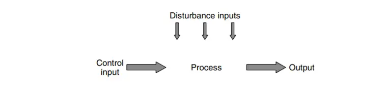
In Figure 2 we see a controller signal (output of figure 1) that will operate on an input to the process, known as the Manipulated Variable or MV. We try to drive the output of the process to a particular value or SP by changing the input. The output may also be affected by other conditions in the process or by external actions such as changes in supply pressures or in the quality of materials being used in the process. These are all regarded as disturbance inputs and our control action will need to overcome their influences as best as possible.
Also Read: Open Loop & Closed Loop System
Ref: Practical Process Control for Engineers and Technicians